1.7 Working with Textures
Having established a foundation in uniforms, let's explore the fascinating realm of texture maps. A texture map is essentially an image wrapped around a 3D geometry mesh. Until now, our renderings have been rather basic—solid color triangles or triangles with gradient colors. They lack the richness and complexity we often encounter in games and advanced graphics applications.
Launch Playground - 1_07_working_with_texturesIn computer graphics and gaming, it's common practice to apply various images to geometries, creating vivid and detailed visuals. This tutorial will demonstrate how to achieve this effect. Implementing textures in a shader relies on uniforms, which is why we covered uniforms in the previous chapter—to lay the groundwork for texture mapping.
@group(0) @binding(0)
var<uniform> offset: vec3<f32>;

struct VertexOutput {
    @builtin(position) clip_position: vec4<f32>,
    @location(0) tex_coords: vec2<f32>,
};

@vertex
fn vs_main(
    @location(0) inPos: vec3<f32>,
    @location(1) inTexCoords: vec2<f32>
) -> VertexOutput {
    var out: VertexOutput;
    out.clip_position = vec4<f32>(inPos + offset, 1.0);
    out.tex_coords = inTexCoords;
    return out;
}
Let's examine the changes in our shader code. In the vertex shader, we've introduced a new attribute at @location(1) called inTexCoords for texture coordinates. Each vertex now has specific texture coordinates associated with it. To pass these coordinates to the fragment stage, we've added a new output value tex_coords in the VertexOutput struct. This ensures proper interpolation of texture coordinates for each fragment.
@group(0) @binding(1)
var t_diffuse: texture_2d<f32>;
@group(0) @binding(2)
var s_diffuse: sampler;

@fragment
fn fs_main(in: VertexOutput) -> @location(0) vec4<f32> {
    return textureSample(t_diffuse, s_diffuse, in.tex_coords);
}
During the fragment stage, these coordinates are used to fetch colors from the texture image. When coordinates fall between texture pixels, interpolation is employed. The exact interpolation method can be configured, with linear and nearest being common choices.
The fragment shader introduces two new uniforms. The first, t_diffuse, of type texture_2d<f32>, represents the actual texture map or image we want to apply. The second, s_diffuse, of type sampler, might seem less intuitive.
A sampler defines behavior rather than providing values. It dictates how we sample the texture's color based on given texture coordinates. When texture coordinates fall between pixels, interpolation is necessary. The sampler allows us to specify our preferred interpolation method. Different methods yield varying results—some produce smooth but slightly blurred effects, while others are sharp but may exhibit aliasing artifacts. The choice depends on the specific use case, and we can explore different sampler types in future chapters.
With these shader updates in place, we're now ready to examine how to supply values for these new uniforms in our JavaScript code.
const response = await fetch('../data/baboon.png');
const blob = await response.blob();
const imgBitmap = await createImageBitmap(blob);
Let's explore the JavaScript aspects of WebGPU programming. Our first task is to create an image. We utilize the fetch API to load a PNG image from the server. Once the server responds, we create a blob from the response body. From this blob, we then generate an image bitmap.
const textureDescriptor = {
    size: { width: imgBitmap.width, height: imgBitmap.height },
    format: 'rgba8unorm',
    usage: GPUTextureUsage.TEXTURE_BINDING | GPUTextureUsage.COPY_DST | GPUTextureUsage.RENDER_ATTACHMENT
};
const texture = device.createTexture(textureDescriptor);

device.queue.copyExternalImageToTexture({ source: imgBitmap }, { texture }, textureDescriptor.size);
With our bitmap prepared, the next step is to create a texture. We begin by defining a texture descriptor. This descriptor requires the width and height of the texture as well as the pixel format. For the usage flags, we must set the TEXTURE_BINDING flag because we intend to use this texture in our shader. It's also necessary to include the COPY_DST and RENDER_ATTACHMENT flags. Both are mandated by the copyExternalImageToTexture helper function. While the WebGPU specification doesn't explicitly detail the reason, we can infer that this function underlies a GPU command submission, possibly involving rendering to the texture to load the image data into the GPU. We'll explore the concept of rendering to texture later, but for now, it's important to remember that whenever we use copyExternalImageToTexture to copy an image to texture, these two additional texture usages are required.
const sampler = device.createSampler({
    addressModeU: 'repeat',
    addressModeV: 'repeat',
    magFilter: 'linear',
    minFilter: 'linear',
    mipmapFilter: 'linear',
});

let shaderModule = shaderModuleFromCode(device, 'shader');
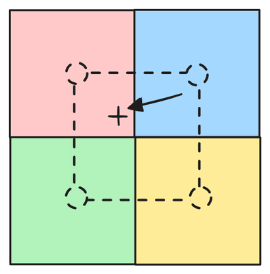
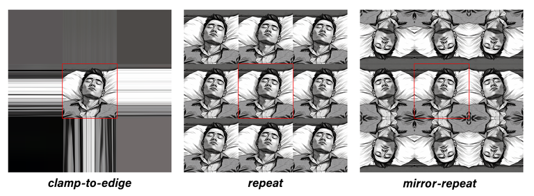
Now, let's create a sampler. The first two parameters, addressModeU and addressModeV, specify how we should sample a texture if the requested texture coordinates fall outside the texture's range. In any texture image, the texture coordinate (0,0) corresponds to its top left corner, while (1,1) corresponds to the bottom right corner. Therefore, any point with both x and y in the range of [0,1] can map to a point on the texture. But what happens if coordinates are outside this range? That's where these two settings come into play. Common options include clamp-to-edge, repeat, and mirror-repeat. clamp-to-edge essentially clamps any value larger than 1 to 1, and any value smaller than 0 to 0. repeat wraps around the coordinates, creating a tiling effect, i.e., a value v that is larger than 1 becomes v-1. mirror-repeat flips the coordinate across the 0 and 1 boundary, such that a value v that's larger than 1 becomes 1 - (v - 1).
In our case, we've chosen repeat, indicating that the texture should be repeated if the coordinates extend beyond the texture's size. This allows us to sample color even when the coordinates exceed the texture's dimensions. As for the filters, we've opted for a linear filter. This provides smooth sampling results, utilizing bilinear interpolation. However, it's worth noting that this choice can sometimes lead to a slightly blurry outcome. We'll explore more examples in future chapters to better understand these choices.
const positionAttribDesc = {
    shaderLocation: 0, // @location(0)
    offset: 0,
    format: 'float32x3'
};

const positionBufferLayoutDesc = {
    attributes: [positionAttribDesc],
    arrayStride: 4 * 3, // sizeof(float) * 3
    stepMode: 'vertex'
};

const texCoordsAttribDesc = {
    shaderLocation: 1, // @location(1)
    offset: 0,
    format: 'float32x2'
};

const texCoordsBufferLayoutDesc = {
    attributes: [texCoordsAttribDesc],
    arrayStride: 4 * 2, // sizeof(float) * 3
    stepMode: 'vertex'
};

const positions = new Float32Array([
    1.0, -1.0, 0.0,
    -1.0, -1.0, 0.0,
    0.0, 1.0, 0.0
]);

let positionBuffer
    = createGPUBuffer(device, positions, GPUBufferUsage.VERTEX);

const texCoords = new Float32Array([
    1.0,
    1.0,
    // 🔴
    0.0,
    1.0,

    0.5,
    0.0,

]);

let texCoordsBuffer
    = createGPUBuffer(device, texCoords, GPUBufferUsage.VERTEX);

const uniformData = new Float32Array([
    0.1, 0.1, 0.1
]);

let uniformBuffer
    = createGPUBuffer(device, uniformData, GPUBufferUsage.UNIFORM);

let uniformBindGroupLayout = device.createBindGroupLayout({
    entries: [
        {
            binding: 0,
            visibility: GPUShaderStage.VERTEX,
            buffer: {}
        },
        {
            binding: 1,
            visibility: GPUShaderStage.FRAGMENT,
            texture: {}
        },
        {
            binding: 2,
            visibility: GPUShaderStage.FRAGMENT,
            sampler: {}
        }
    ]
});

let uniformBindGroup = device.createBindGroup({
    layout: uniformBindGroupLayout,
    entries: [
        {
            binding: 0,
            resource: {
                buffer: uniformBuffer
            }
        },
        {
            binding: 1,
            resource: texture.createView()
        },
        {
            binding: 2,
            resource:
                sampler

        }
    ]
});
The remaining code structure remains largely the same. We still create the uniform buffer, but now it only contains the offset value. When we create the bind group, for the @binding(0), we continue to provide the offsets via the uniform buffer. However, for the texture, we're using a texture view as its resource. And for the sampler, we simply provide the sampler as the resource.
passEncoder = commandEncoder.beginRenderPass(renderPassDesc);
passEncoder.setViewport(0, 0, canvas.width, canvas.height, 0, 1);
passEncoder.setPipeline(pipeline);
passEncoder.setBindGroup(0, uniformBindGroup);
passEncoder.setVertexBuffer(0, positionBuffer);
passEncoder.setVertexBuffer(1, texCoordsBuffer);
passEncoder.draw(3, 1);
passEncoder.end();
The rest of the code follows the previous pattern. One notable difference is that we provide the texture coordinates by calling setVertexBuffer for @location(1) with the texture coordinate buffer.
With these changes in place, we've effectively integrated a texture into our shader, opening up a world of possibilities for more visually captivating graphics.