1.4 Using Different Vertex Colors
In this tutorial, we're making another subtle modifications to our previous example. Rather than hard-coding colors in the shader, we'll pass vertex colors as data into the shader, demonstrating a more flexible and realistic approach to 3D rendering.
Launch Playground - 1_04_different_vertex_colorsLet's examine the changes in our shader code. In addition to the position attribute at @location(0), we've introduced a new input parameter at @location(1), which we've named inColor. This inColor parameter is a vector of three floats representing the Red, Green, and Blue components of the color. In the vertex stage, where we previously hard-coded the out.color field, we now simply assign the input inColor to it. The rest of the shader code remains unchanged.
This example serves to illustrate how we can pass multiple attributes, beyond just vertex positions, using different location indices. It's a crucial concept in shader programming, allowing for more complex and varied rendering effects.
struct VertexOutput {
    @builtin(position) clip_position: vec4<f32>,
    @location(0) color: vec3<f32>,
};

@vertex
fn vs_main(
    @location(0) inPos: vec3<f32>,
    @location(1) inColor: vec3<f32>
) -> VertexOutput {
    var out: VertexOutput;
    out.clip_position = vec4<f32>(inPos, 1.0);
    out.color = inColor;
    return out;
}

@fragment
fn fs_main(in: VertexOutput) -> @location(0) vec4<f32> {
    return vec4<f32>(in.color, 1.0);
}
By assigning different colors to different vertices, we're now in a position to address the interesting question we raised earlier: how are fragment colors generated for those fragments located in the middle of a triangle? This setup will allow us to observe the GPU's color interpolation in action, providing a visual demonstration of how data is processed between the vertex and fragment stages of the rendering pipeline.
Now, let's explore how to set up the pipeline for our new shader. The new pipeline is quite similar to the previous one, with the key difference being that we now need to create a color buffer containing colors for all vertices and feed it into our pipeline.
The steps involved closely mirror how we handled the position buffer. First, we create a color attribute descriptor. Note that we set shaderLocation to 1, corresponding to the inColor attribute at @location(1) in our shader. The format for the color attribute remains a vector of three floats.
const colorAttribDesc = {
    shaderLocation: 1, // @location(1)
    offset: 0,
    format: 'float32x3'
};

const colorBufferLayoutDesc = {
    attributes: [colorAttribDesc],
    arrayStride: 4 * 3, // sizeof(float) * 3
    stepMode: 'vertex'
};
const colors = new Float32Array([
    1.0,
    0.0,
    0.0, // 🔴
    0.0,
    1.0,
    0.0, // 🟢
    0.0,
    0.0,
    1.0 // 🔵
]);

let colorBuffer = createGPUBuffer(device, colors, GPUBufferUsage.VERTEX);
Next, we create the buffer layout descriptor, which informs the pipeline how to interpret the color buffer for each vertex. We assign the color attribute descriptor to the attributes field. The arrayStride is set to 4 * 3 because a float occupies 4 bytes, and we have 3 floats for each color. The stepMode is set to vertex because each vertex will have one color.
After defining the RGB data in CPU memory using a Float32Array (with the first vertex being red, the second green, and the third blue), we proceed to create a GPU buffer and copy the data to the GPU.
Let's recap the process of creating and populating the GPU buffer:
We define a buffer descriptor, specifying the buffer size and setting the usage flag as
VERTEXsince we'll use the color attribute in the vertex stage.We set
mappedAtCreationto true, allowing immediate data copying upon buffer creation.We create the GPU buffer and, using the mapped buffer range, create a mirrored buffer in CPU memory.
We copy the color data into this mapped buffer.
Finally, we unmap the buffer, signaling that the data transfer is complete.
In our sample code, you might notice that we don't explicitly see these steps. This is because this process is a common procedure that we need to perform many times throughout our WebGPU programs. To streamline our code and reduce repetition, I've created a utility function to encapsulate these steps.
As previously mentioned, WebGPU can be quite verbose in its syntax. It's often a good practice to wrap common code blocks into reusable utility functions. This approach not only reduces our workload but also makes our code more readable and maintainable.
The createGPUBuffer function I've created encapsulates all these steps into a single, reusable function. Here's how it's defined:
function createGPUBuffer(device, buffer, usage) {
    const bufferDesc = {
        size: buffer.byteLength,
        usage: usage,
        mappedAtCreation: true
    };
    //console.log('buffer size', buffer.byteLength);
    let gpuBuffer = device.createBuffer(bufferDesc);
    if (buffer instanceof Float32Array) {
        const writeArrayNormal = new Float32Array(gpuBuffer.getMappedRange());
        writeArrayNormal.set(buffer);
    }
    else if (buffer instanceof Uint16Array) {
        const writeArrayNormal = new Uint16Array(gpuBuffer.getMappedRange());
        writeArrayNormal.set(buffer);
    }
    else if (buffer instanceof Uint8Array) {
        const writeArrayNormal = new Uint8Array(gpuBuffer.getMappedRange());
        writeArrayNormal.set(buffer);
    }
    else if (buffer instanceof Uint32Array) {
        const writeArrayNormal = new Uint32Array(gpuBuffer.getMappedRange());
        writeArrayNormal.set(buffer);
    }
    else {
        const writeArrayNormal = new Float32Array(gpuBuffer.getMappedRange());
        writeArrayNormal.set(buffer);
        console.error("Unhandled buffer format ", typeof gpuBuffer);
    }
    gpuBuffer.unmap();
    return gpuBuffer;
}
At this point, we've successfully duplicated the color values on the GPU, ready for use in our shader.
const pipelineDesc = {
    layout,
    vertex: {
        module: shaderModule,
        entryPoint: 'vs_main',
        buffers: [positionBufferLayoutDesc, colorBufferLayoutDesc]
    },
    fragment: {
        module: shaderModule,
        entryPoint: 'fs_main',
        targets: [colorState]
    },
    primitive: {
        topology: 'triangle-list',
        frontFace: 'cw',
        cullMode: 'back'
    }
};

pipeline = device.createRenderPipeline(pipelineDesc);
commandEncoder = device.createCommandEncoder();

passEncoder = commandEncoder.beginRenderPass(renderPassDesc);
passEncoder.setViewport(0, 0, canvas.width, canvas.height, 0, 1);
passEncoder.setPipeline(pipeline);
passEncoder.setVertexBuffer(0, positionBuffer);
passEncoder.setVertexBuffer(1, colorBuffer);
passEncoder.draw(3, 1);
passEncoder.end();

device.queue.submit([commandEncoder.finish()]);
After creating our buffers, we define the pipeline descriptor. The key difference from our previous example is the addition of colorBufferLayoutDescriptor to the buffers list in the vertex stage. This informs the pipeline that we're now using two vertex buffers: one for positions and another for colors.
When encoding our render commands, we now need to set two vertex buffers. We use setVertexBuffer(0, positionBuffer) for the position data and setVertexBuffer(1, colorBuffer) for the color data. The indices 0 and 1 correspond to the buffer layouts when defining the pipeline descriptor. The rest of the rendering process remains largely unchanged.
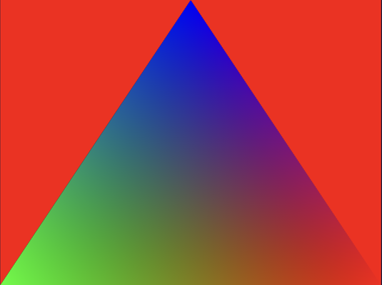
Upon running this code, we're presented with a visually interesting result: a colorful triangle. Each vertex is rendered with its specified color - red, green, and blue. However, the most interesting aspect is what happens between these vertices. We observe a smooth transition of colors across the triangle's surface.
This automatic color blending is a feature performed by the GPU, a process we refer to as interpolation. It's important to note that this interpolation isn't limited to colors; any value we output at the vertex stage will be interpolated by the GPU to assign appropriate values for every fragment, particularly for those not located directly at the vertices.
The interpolation for a fragment's values is calculated based on its relative distance to the vertices, following a bilinear scheme. This mechanism is incredibly useful because, considering there are typically far more fragments than vertices in a scene, it would be impractical to specify values for all fragments individually. Instead, we rely on the GPU to generate these values efficiently based on the values defined only at each vertex.
This interpolation technique is a fundamental concept in computer graphics, enabling smooth transitions and gradients across surfaces with minimal input data.