5.2 Toon Shading
Rendering realism is not always the goal in graphics. Artistic styles, such as painting or cartoon-like effects, can be equally compelling. In this tutorial, we will explore a simple cartoon-style rendering technique.
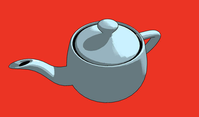
Launch Playground - 5_02_toon_shadingSpecifically, we will focus on implementing two effects: first, adding a silhouette to a model, and second, adjusting the shader to create a painterly style where colors don’t change gradually.
Let's start with the silhouette. There are several methods to achieve this effect, each with its own pros and cons. One method involves detecting discontinuities in screen space. This approach requires rendering the scene first with additional metadata, such as surface normals, depth, and colors. In a second pass, these properties are analyzed to detect discontinuities, which are then highlighted as silhouettes. While effective, this method can be resource-intensive and sensitive to the size of objects in the image space.
In this tutorial, we'll use a simpler approach: enlarging the object slightly and flipping it inside out. The enlarged object is shaded in pure black to create the silhouette effect. This method avoids the need for expensive screen-space post-processing and is commonly used in games due to its efficiency.
Enlarging an object can be achieved by offsetting each vertex away from the object's center by a fixed percentage. While this approach works well for roughly spherical objects, it can produce less satisfactory results for long or complex shapes. In such cases, areas further from the center may stretch more than those closer, leading to imperfect silhouettes.
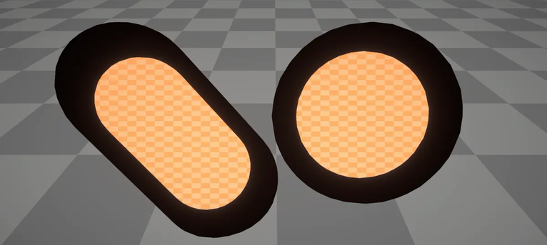
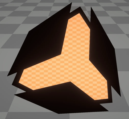
A better approach is to inflate the object at each vertex along the vertex normal. It's important to use the vertex normal rather than the surface normal for this process. The vertex normal is computed by averaging the adjacent surface normals, which provides a smoother and more accurate result for sharp features. If you were to use the surface normal directly, you might introduce artifacts, as surfaces sharing the same vertex may not align perfectly. Using vertex normals helps to minimize these artifacts and achieve a more consistent silhouette.
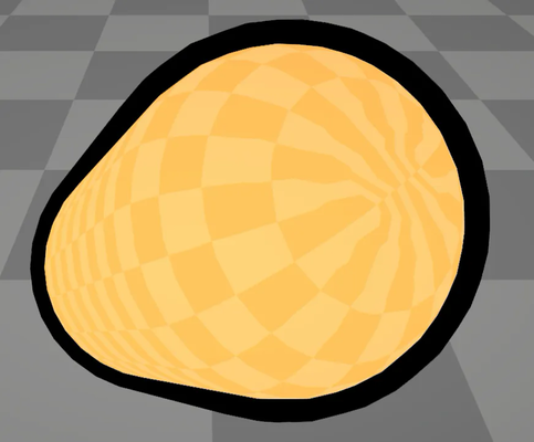
However, this method does come with its own drawback: the silhouette's appearance is sensitive to the viewing distance. When close to the object, the silhouette may appear overly thick, while from a distance, it might become too thin and less noticeable. This variation in silhouette thickness can affect the overall visual impact of the cartoon-style rendering.
What we want is a uniformly wide silhouette that remains consistent regardless of the viewing angle and distance. This can be achieved by working in clip space. Our approach involves projecting the vertex normals onto the clip plane, and then, in clip space, offsetting the vertex positions based on these normals. Since both the vertex normal and vertex position are in 2D in clip space, and this step occurs after the perspective projection, the silhouette thickness remains unaffected by the viewing angle or distance.
To summarize, rendering a silhouette involves two key steps. First, render the slightly inflated object in black or the silhouette color, and then render the original object on top. There are two methods to achieve this:
In the first method, use two passes. During the first pass, render the inflated object in the silhouette color but without writing to the depth buffer. This ensures that the inflated object, being larger, does not occlude the normal object. In the second pass, render the object normally on top of the silhouette.
The second method is simpler but less intuitive. Flip the inflated object inside out and render only its back faces in the silhouette color, while simultaneously rendering the object normally with depth testing enabled. By flipping the object, the front side of the inflated object is effectively peeled away, ensuring it does not occlude the normally rendered object. This method allows for achieving the silhouette effect in a single rendering pass.
Let's dive into the implementation:
@group(0) @binding(0)
var<uniform> modelView: mat4x4<f32>;
@group(0) @binding(1)
var<uniform> projection: mat4x4<f32>;
@group(0) @binding(2)
var<uniform> normalMatrix: mat4x4<f32>;
@group(0) @binding(3)
var<uniform> screenDim: vec2<f32>;

struct VertexOutput {
    @builtin(position) clip_position: vec4<f32>,
};

@vertex
fn vs_main(
    @location(0) inPos: vec3<f32>,
    @location(1) inNormal: vec3<f32>
) -> VertexOutput {
    var out: VertexOutput;
    out.clip_position = projection * modelView * vec4<f32>(inPos, 1.0);
    var clip_normal:vec4<f32> = projection * normalMatrix * vec4<f32>(inNormal, 0.0);

    out.clip_position =vec4<f32>( out.clip_position.xy + normalize(clip_normal.xy)*6.4/screenDim * out.clip_position.w,out.clip_position.zw );
    return out;
}

// Fragment shader

@fragment
fn fs_main(in: VertexOutput) -> @location(0) vec4<f32> {
    return vec4<f32>( 0.0,0.0,0.0,1.0);
}
The shader implementation inflates the object in clip space. The vertex shader receives two parameters: the vertex position and the vertex normal, both in 3D coordinates. We first convert the vertex position to clip space as usual. For the normal vector, we apply the normal matrix followed by the projection. Note that the w component is set to 0.0 because it represents a vector rather than a point.
Next, we proceed to inflate the clip space position. Since the silhouette is represented in 2D, we leave the z and w components unchanged. For the x and y components, we offset them by normalize(clip_normal.xy) * 6.4 / screenDim * out.clip_position.w. Here, dividing the clip space normal by the screen dimension compensates for screen size and aspect ratio, ensuring that the silhouette width remains consistent across different screen sizes and aspect ratios. Multiplying by out.clip_position.w is necessary because the graphics pipeline divides the clip space position by w when converting it to normalized device coordinates. To prevent changes in silhouette thickness during this conversion, we pre-multiply by w.
The fragment shader is straightforward; it outputs pure black pixels to render the silhouette.
Now, let’s examine the JavaScript code:
let { positionBuffer, normalBuffer, indexBuffer, indexSize } = await loadObj(device, '../data/teapot.obj');
this.positionBuffer = positionBuffer;
// The normal buffer contains vertex normals calculated as averages of adjacent surface normals.
this.normalBuffer = normalBuffer;
this.indexBuffer = indexBuffer;
this.indexSize = indexSize;
const outlinePipelineDesc = {
    layout: device.createPipelineLayout(outlinePipelineLayoutDesc),
    vertex: {
        module: shaderModuleOutline,
        entryPoint: 'vs_main',
        buffers: [positionBufferLayoutDesc, normalBufferLayoutDesc]
    },
    fragment: {
        module: shaderModuleOutline,
        entryPoint: 'fs_main',
        targets: [colorState]
    },
    primitive: {
        topology: 'triangle-list',
        frontFace: 'ccw',
        cullMode: 'front'
    },
    depthStencil: {
        depthWriteEnabled: true,
        depthCompare: 'less',
        format: 'depth32float'
    }
}
When loading the OBJ file, we have already established the normal buffer containing vertex normals, which are calculated as the average of adjacent surface normals. When setting up the pipeline for rendering the outline, we configure the cullMode to front to remove the front side of the inflated object. Additionally, depth testing is enabled to ensure proper depth handling.
In the second part of this tutorial, we’ll focus on achieving a painterly shading effect. Unlike realistic rendering, painterly styles often feature discrete color transitions rather than smooth gradients. These styles may use "false" colors that do not adhere to physical lighting equations, aiming instead for a specific artistic effect.
To create this painterly effect, we introduce a lookup table (LUT) to discretize colors. While we continue to use the Phong shading algorithm for lighting calculations, we no longer directly compute the final color. Instead, we calculate the light intensity as a single value and use a pre-built LUT to convert this intensity into colors. Our 1D LUT maps values in the range [0,1] to arbitrary RGB colors. In our setup, the 1D texture contains bands of false colors, which will be used to render the final image.
Let’s examine the shader used for this effect. This shader is based on the shadow map shader but adapted to include the LUT for painterly shading.
// Instead of setting colors as RGB, we use scalars here as we only want to calculate intensity.
const diffuseConstant:f32 = 1.0;
const specularConstant:f32 = 0.0;
const ambientConstant:f32 = 0.0;
// We apply the same Phong shading, but instead of deriving the final color, we obtain an intensity.
var intensity:f32 = max(dot(-lightDir, n), 0.0)* diffuseConstant + specular(-lightDir, viewDir, n, shininess) * specularConstant;
// With the light intensity, we look up the final color.
var diffuse:vec3<f32> = textureSample(t_shade, s_shade, intensity * visibility).xyz;
And finally, let's see, on the javascript side, how this 1D lookup texture is set up.
// 1D texture, width is hardcoded to 128.
const shadeTextureDesc = {
    size: [128],
    dimension: '1d',
    format: "rgba8unorm",
    usage: GPUTextureUsage.COPY_DST | GPUTextureUsage.TEXTURE_BINDING
};
// Populate color data. This lookup table defines 4 color bands.
let shadeTextureColors = [];
for (let i = 0; i < 128; ++i) {
    if (i < 40) {
        shadeTextureColors.push(95);
        shadeTextureColors.push(121);
        shadeTextureColors.push(127);
        shadeTextureColors.push(255);
    }
    else if (i >= 40 && i < 80) {
        shadeTextureColors.push(143);
        shadeTextureColors.push(181);
        shadeTextureColors.push(191);
        shadeTextureColors.push(255);
    }
    else if (i >= 80 && i < 124) {
        shadeTextureColors.push(191);
        shadeTextureColors.push(242);
        shadeTextureColors.push(255);
        shadeTextureColors.push(255);
    }
    else {
        shadeTextureColors.push(255);
        shadeTextureColors.push(255);
        shadeTextureColors.push(255);
        shadeTextureColors.push(255);
    }
}
// Create a texture and copy data to it.
let shadeTexture = device.createTexture(shadeTextureDesc);
device.queue.writeTexture({ texture: shadeTexture }, new Uint8Array(shadeTextureColors), {
    offset: 0,
    bytesPerRow: 128 * 4,
    rowsPerImage: 1
}, { width: 128 });
// Wait for completion.
await device.queue.onSubmittedWorkDone();
Together with the outline shader, we now have the toon shading effect: