5.1 Shadow Mapping
In previous lessons, we covered lighting, but achieving realism requires more than just lighting alone. Our current lighting model is quite basic: if a surface normal faces a light source, the surface is illuminated. However, in reality, objects cast shadows, meaning that a surface area blocked from a light source by an object should remain dark, even if its normal faces the light.
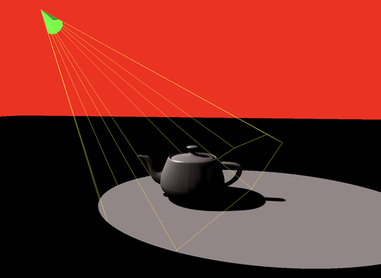
Launch Playground - 5_01_shadow_mapsIn this tutorial, we will explore how to implement shadows using a technique called shadow mapping. This technique allows us to create hard shadows, where the boundary between shadowed and lit areas is well-defined. Hard shadows can be produced by simulating an idealized point light source but do not address more complex scenarios like soft shadows that result from nearby area light sources.
The concept of shadow mapping is straightforward. First, we render the scene from the light source’s perspective to generate a depth map. This depth map records the shortest distance from the light source to all visible surfaces directly illuminated by the light.
Later, when rendering the scene from the camera’s perspective, we calculate the distance from each fragment to the light source and compare it with the corresponding value in the depth map. If the distance is equal to or less than the depth map value, the fragment is lit by the light source. Otherwise, if the distance is greater, the fragment is considered occluded and is rendered in a darker color.
Our code will build on the lighting code from before. The first step is to adjust the light from a point light to a spot light. Unlike a point light, which emits rays in all directions, a spot light has a narrow cone of illumination, affecting only the scene within this cone.
When rendering from the light’s perspective, we need to define a view frustum compatible with the spot light.
Implementing a spot light is straightforward. We only need to make a few adjustments to our original point light shader:
if (face) {
    var wldLoc2light:vec3<f32> =   in.wldLoc-lightLoc;
    if (align > 0.9) {
        var radiance:vec3<f32>  = ambientColor.rgb * ambientConstant +
            diffuse(-lightDir, n, diffuseColor.rgb)* diffuseConstant +
            specular(-lightDir, viewDir, n, specularColor.rgb, shininess) * specularConstant;

        return vec4<f32>(radiance * visibility ,1.0);
    }
}
return vec4<f32>( 0.0,0.0,0.0,1.0);
In this shader, wldLoc2light represents the vector from the fragment’s world location to the light’s location, while lightDir is the light direction vector. We compute the dot product of these two vectors and only illuminate the fragment if the dot product exceeds a threshold of 0.9, indicating that the angle between the vectors is sufficiently small. Both vectors are in the world coordinate system and have not yet been transformed by the projection matrix:
var wldLoc:vec4<f32> = modelView * vec4<f32>(inPos, 1.0);
out.clip_position = projection * wldLoc;
out.wldLoc = wldLoc.xyz / wldLoc.w;
out.inPos = inPos;
var lightLoc:vec4<f32> = modelView * vec4<f32>(lightDirection, 1.0);
out.lightLoc = lightLoc.xyz / lightLoc.w;
After converting the point light to a spot light, the next step is to generate a depth map, or shadow map, by rendering the scene from a virtual camera aligned with the light.
Let’s take a step-by-step approach: first, we’ll dump and visualize the depth map before applying it in the final step to create the shadow effect.
@group(0) @binding(0)
var<uniform> modelView: mat4x4<f32>;
@group(0) @binding(1)
var<uniform> projection: mat4x4<f32>;

struct VertexOutput {
    @builtin(position) clip_position: vec4<f32>,
    @location(0) depth: f32
};

@vertex
fn vs_main(
    @location(0) inPos: vec3<f32>
) -> VertexOutput {
    var out: VertexOutput;
    var wldLoc:vec4<f32> = modelView * vec4<f32>(inPos, 1.0);
    out.clip_position = projection * wldLoc;
    out.depth = out.clip_position.z / out.clip_position.w;
    return out;
}

struct FragOutputs {
    @builtin(frag_depth) depth: f32,
    @location(0) color: vec4<f32>
  }

// Fragment shader
@fragment
fn fs_main(in: VertexOutput,   @builtin(front_facing) isFront: bool) -> FragOutputs {
    var out:FragOutputs;
    if (isFront) {
        out.depth = in.depth;
    }
    else {
        out.depth = in.depth -0.001;
    }
    out.color = vec4<f32>(0.0,1.0,0.0,1.0);
    return out;
}
The shader presented is straightforward and should be familiar. To clarify, the depth map is rendered from the perspective of the light, so the modelView and projection matrices are derived from the light's viewpoint rather than the camera's. In a standard fragment shader, depth calculations are handled automatically by the graphics pipeline. However, in this case, we need to manually calculate and write the depth value to a texture map. This is done using the clip space position, where the z-value represents the depth.
A notable detail in the shader code is:
if (isFront) {
    out.depth = in.depth;
}
else {
    out.depth = in.depth -0.001;
}
Here, the shader checks if the current fragment is front-facing. If it is, the depth value is output directly. If the fragment is not front-facing, the depth is slightly adjusted by moving it closer to the camera. This adjustment helps to mitigate artifacts caused by numerical precision issues. We can revisit and assess the impact of this adjustment after implementing the full program.
Next, we turn to the JavaScript side to understand how parameters are calculated and passed to the shader. Specifically, we need to create a model-view matrix for the light, ensuring it circles around the teapot. For each rendering iteration, we adjust the light’s angle and recalculate the model-view matrix accordingly.
let lightDir = glMatrix.vec3.fromValues(Math.cos(angle) * 8.0, Math.sin(angle) * 8.0, 10);
let lightDirectionUniformBufferUpdate = createGPUBuffer(device, lightDir, GPUBufferUsage.COPY_SRC);
spotlight.upsertSpotLight(spotLightId, lightDir, glMatrix.vec3.fromValues(-Math.cos(angle) * 8.0, -Math.sin(angle) * 8.0, -10), glMatrix.vec3.fromValues(0.0, 1.0, 0.0));
spotlight.refreshBuffer(device);

let lightModelViewMatrix = glMatrix.mat4.lookAt(glMatrix.mat4.create(),
    glMatrix.vec3.fromValues(Math.cos(angle) * 8.0, Math.sin(angle) * 8.0, 10),
    glMatrix.vec3.fromValues(0, 0, 0), glMatrix.vec3.fromValues(0.0, 0.0, 1.0));

let lightModelViewMatrixUniformBufferUpdate = createGPUBuffer(device, lightModelViewMatrix, GPUBufferUsage.COPY_SRC);
For the projection matrix of the light, which does not change frequently, we initialize it only once:
let lightProjectionMatrix = glMatrix.mat4.perspective(glMatrix.mat4.create(),
    Math.acos(0.9) * 2.0, 1.0, 1.0, 100.0);

let lightProjectionMatrixUniformBuffer = createGPUBuffer(device, lightProjectionMatrix, GPUBufferUsage.UNIFORM);
Here, the vertical view angle is hardcoded as Math.acos(0.9) * 2.0, corresponding to the 0.9 visibility threshold used in the shader.
To visualize the shadow map, we use the following code:
let copiedBuffer = createGPUBuffer(device, new Float32Array(1024 * 1024), GPUBufferUsage.COPY_DST | GPUBufferUsage.MAP_READ);
commandEncoder.copyTextureToBuffer({ texture: lightDepthTexture, origin: { x: 0, y: 0 } }, { buffer: copiedBuffer, bytesPerRow: 1024 * 4 }, { width: 1024, height: 1024 });
if (!hasDumped) {
    hasDumped = true;
    await copiedBuffer.mapAsync(GPUMapMode.READ, 0, 1024 * 1024 * 4);

    const d = new Float32Array(copiedBuffer.getMappedRange());
    const x = new Uint8ClampedArray(1024 * 1024 * 4);
    let maxv = -900;
    let minv = 900;
    for (let i = 0; i < 1024 * 1024; ++i) {
        const v = d[i];

        if (maxv < v) {
            maxv = v;
        }
        if (minv > v) {
            minv = v;
        }
        x[i * 4] = v * 255.0;
        x[i * 4 + 1] = v * 255.0;
        x[i * 4 + 2] = v * 255.0;
        x[i * 4 + 3] = v * 255.0;
    }
    copiedBuffer.unmap();
    const imageData = new ImageData(x, 1024, 1024);
    imagedataToImage(imageData);
    console.log("max min: ", maxv, minv);
}
This code reads the shadow map from the GPU into a buffer called copiedBuffer, which is initially in Float32 format. It then converts this data to Uint8 format for visualization. The resulting ImageData is used to create an image for further analysis.

In the final step, we use the shadow map to create shadows. Let's first examine the shader code responsible for this:
var fragmentPosInShadowMapSpace: vec4<f32> = lightProjectionMatrix * lightModelViewMatrix * vec4(in.inPos, 1.0);
fragmentPosInShadowMapSpace = fragmentPosInShadowMapSpace / fragmentPosInShadowMapSpace.w;
var depth: f32 = fragmentPosInShadowMapSpace.z;
Here, inPos represents the vertex position. We calculate the depth from the light's perspective using the light's projection and model-view matrices. This approach mirrors the depth calculation method used previously in the shader.
var uv:vec2<f32> = 0.5*(fragmentPosInShadowMapSpace.xy + vec2(1.0,1.0));

var visibility = 0.0;
    let oneOverShadowDepthTextureSize = 1.0 / 1024.0;
    for (var y = -2; y <= 2; y++) {
      for (var x = -2; x <= 2; x++) {
        let offset = vec2<f32>(vec2(x, y)) * oneOverShadowDepthTextureSize;

        visibility += textureSampleCompare(
            t_depth, s_depth,
            vec2(uv.x, 1.0-uv.y) + offset,depth  - 0.0003
        );
      }
    }
    visibility /= 25.0;
The uv coordinates are calculated from fragmentPosInShadowMapSpace, transforming them from [-1, 1] range to [0, 1] range.
To enhance visual quality, rather than directly comparing a fragment's depth with the corresponding value in the shadow map, we sample a 5x5 pixel neighborhood around the fragment’s position to compute an average visibility. The shadow map is fixed at 1024x1024 pixels, so each pixel's width and height is 1.0 / 1024.0. We use this unit size to adjust the UV coordinates with an offset, transforming the coordinates using: vec2(uv.x, 1.0-uv.y) + offset. This adjustment flips the y-coordinate because, in the texture map, the v-coordinate ranges from 0 to 1 from top to bottom, whereas in screen space, the y-axis is flipped.
The texture sampling uses a comparison function called textureSampleCompare. This function requires an additional reference value, depth - 0.0003, for comparison. If the depth value in the shadow map is less than this reference value, the function returns 1.0; otherwise, it returns 0.0. This comparison method is configured in the JavaScript code, which we will review later. In the shader, the comparison is set to "less," meaning a sample value less than the reference will pass the comparison.
The use of a small offset (0.0003) is crucial for preventing artifacts caused by numerical errors. For instance, if a ball is illuminated and no other objects are present, the ball should ideally be lit. However, due to numerical errors, some fragments may have depths that are either less than or greater than those in the shadow map, leading to random shadow artifacts. By adjusting the depth slightly forward, we ensure that the surface’s depth is always smaller than its own depth value in the shadow map, preventing self-occlusion.
Finally, we determine the surface color based on visibility. The radiance calculation occurs only if two conditions are met: the fragment is within the spot light's frustum, and it is not in shadow.
if (face) {
    var wldLoc2light:vec3<f32> =   in.wldLoc-lightLoc;
    if (align > 0.9) {
        var radiance:vec3<f32>  = ambientColor.rgb * ambientConstant +
            diffuse(-lightDir, n, diffuseColor.rgb)* diffuseConstant +
            specular(-lightDir, viewDir, n, specularColor.rgb, shininess) * specularConstant;

        return vec4<f32>(radiance * visibility ,1.0);
    }
}
return vec4<f32>( 0.0,0.0,0.0,1.0);
Let’s explore the impact of removing some of the adjustments we've made in the code and the resulting artifacts.
Firstly, removing the offset applied to the depth for back-facing surfaces:
if (isFront) {
    out.depth = in.depth;
}
else {
    out.depth = in.depth -0.001;
}
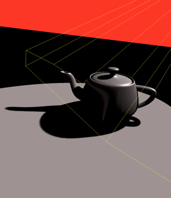
When the offset is removed, back-facing surfaces use the same depth value as front-facing surfaces. This can lead to visual artifacts because the depth test may incorrectly consider some back-facing fragments as nearer than they actually are, resulting in unexpected shadowing or light leakage. The artifact image illustrates these issues clearly.
var uv:vec2<f32> = 0.5*(fragmentPosInShadowMapSpace.xy + vec2(1.0,1.0));

var visibility = 0.0;
    let oneOverShadowDepthTextureSize = 1.0 / 1024.0;
    for (var y = -2; y <= 2; y++) {
      for (var x = -2; x <= 2; x++) {
        let offset = vec2<f32>(vec2(x, y)) * oneOverShadowDepthTextureSize;

        visibility += textureSampleCompare(
            t_depth, s_depth,
            vec2(uv.x, 1.0-uv.y) + offset,depth  - 0.0003
        );
      }
    }
    visibility /= 25.0;
Secondly, if we sample the shadow map using only a single sample instead of averaging a neighborhood, the depth comparison is performed directly without smoothing:
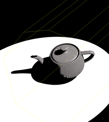
Using a single sample can introduce significant aliasing and noise, especially in areas with complex shadow details. The lack of neighborhood averaging means that small variations in depth can cause inconsistent shadowing, leading to a more pixelated and less smooth shadow effect, as shown in the artifact image.
Lastly, removing the 0.0003 hack that offsets the depth to avoid self-occlusion:
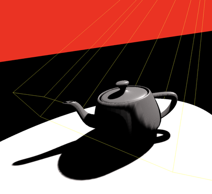
Without this offset, the depth comparison might fail in cases where the depth values from the fragment and the shadow map are very close but not identical due to numerical precision issues. This can cause artifacts where parts of the surface incorrectly appear shadowed or illuminated, as the fragment's depth could inadvertently be considered to be behind itself in the shadow map, leading to incorrect self-shadowing effects. The artifact image highlights these issues where surfaces appear improperly shadowed or lit.