2.4 Text Rendering
The complexity of text rendering in graphics APIs like WebGPU often surprises developers. Despite its fundamental importance in various 3D applications—from user interfaces to visualization labels and 2D game content—text rendering is not a built-in function in these APIs. Instead, it demands significant effort to implement effectively.
This chapter will introduce a basic approach to text rendering while providing insight into the requirements for a full-featured system and the trade-offs between different methodologies.
A comprehensive text rendering process involves several intricate steps. When rendering text, the system must first determine which font files to use. As individual font files typically cover only a subset of characters for one or a few languages, a fallback mechanism becomes necessary. For instance, when rendering a mix of English and Chinese characters, the system may need to use multiple font files to cover all the required glyphs.
Font files contain databases of glyphs and their measurements. It's crucial to understand that glyphs are not always equivalent to characters; they can be partial elements used to assemble characters. For example, in an emoji font file, a smiling face wearing sunglasses could be represented by separate face and sunglasses glyphs. This distinction significantly increases the complexity of font rendering.
The text shaping process transforms characters from their basic forms (glyphs) into contextually appropriate forms. It considers factors such as font styles, ligatures, character positioning, and language-specific rules. The complexity increases when dealing with multiple fonts and languages simultaneously.
Font rasterization presents another challenge. Most glyphs are stored as geometric data, such as line segments and curves, which allows for immune resizing. However, others, particularly emojis, might be in bitmap format, essentially small pictures. A robust rendering function must seamlessly integrate these different formats.
To optimize performance, text rendering systems often implement character caches. This approach establishes a lookup table for previously seen characters, avoiding repeated rasterization. While this is more efficient for languages with small alphabets, it poses challenges for languages like Chinese with numerous characters. Additionally, if the system needs to handle font resizing, the cache must be invalidated to re-render characters at the correct resolution.
For longer text passages, considerations such as text wrapping and reflowing become necessary, especially when the text container's size can change.
Given this complexity, developers rarely implement text rendering from scratch. While operating systems often provide implementations, finding a good cross-platform solution can be challenging. There are libraries available for specific rendering stages, such as text shaping, but many are designed for C++ environments, limiting options for web development.
In 3D graphics contexts, trade-offs are often necessary. Games might limit support to English to simplify character caching, while terminal or IDE-type applications might opt for monospaced fonts to streamline text shaping.
Launch Playground - 2_04_textIn this tutorial, we explore a basic implementation of text rendering. Our approach leverages a 2D canvas to draw text and create a texture map, utilizing the web browser's existing text functionality to handle the complexities previously discussed. While this method simplifies the process, it comes with certain limitations.
For text-heavy applications, this approach can quickly exhaust GPU memory due to the creation of numerous texture maps. Additionally, dynamic text content may suffer from performance issues as rasterizing text and creating texture maps repeatedly can be time-consuming. Furthermore, we are constrained to the font styles available in a 2D context. Despite these drawbacks, this method is well-suited for visualization use cases, such as rendering labels or simple user interfaces.
Let's examine the code that implements this approach:
function printText(device, text) {
    const width = 320;
    const height = 240;
    const canvas = new OffscreenCanvas(width, height);
    const ctx = canvas.getContext("2d");
    ctx.clearRect(0, 0, width, height);
    ctx.globalAlpha = '0.5';
    ctx.font = 'bold 32px Arial';
    ctx.fillStyle = 'white';
    const textMeasure = ctx.measureText(text); // TextM

    console.log("texture measure", textMeasure);
    console.log("width", Math.ceil(textMeasure.width))
    ctx.fillText(text, 0, 28);

    const textureDescriptor = {
        size: { width: nearestPowerOf2(Math.ceil(textMeasure.width)), height: 32 },
        format: 'rgba8unorm',
        usage: GPUTextureUsage.TEXTURE_BINDING | GPUTextureUsage.COPY_DST | GPUTextureUsage.RENDER_ATTACHMENT
    };

    const texture = device.createTexture(textureDescriptor);
    device.queue.copyExternalImageToTexture({ source: canvas, origin: { x: 0, y: 0 } }, { texture }, textureDescriptor.size);

    return {texture, w: textMeasure.width / textureDescriptor.size.width, rw: textMeasure.width};
}
This function takes a piece of text as input, renders it using an offscreen canvas, and then loads the result onto a texture map. We begin by defining a size large enough to accommodate the text we intend to render. This can be challenging for dynamically created text, such as user input, highlighting another limitation of this method. However, for our example with predetermined static text, we can select an adequate size through trial and error.
We create an offscreen canvas and a 2D context based on this size. After configuring the font and fillStyle, we measure the text using the measureText call to determine the required texture size. It's important to note that the RENDER_ATTACHMENT usage is necessary for calling copyExternalImageToTexture. Finally, we load the canvas content onto the texture map and return it.
The rendering process closely resembles that of the texture map tutorial, with one key difference: we're now rendering a transparent texture. To achieve proper rendering, we must enable alpha blending.
const colorState = {
    format: 'bgra8unorm',
    blend: {
        alpha: {
            operation: "add",
            srcFactor: 'one',
            dstFactor: 'one-minus-src',
        },
        color: {
            operation: "add",
            srcFactor: 'one',
            dstFactor: 'one-minus-src',
        }
    }
};
Let's look at how to define the pipeline. Here, I'll omit what we've already learned and focus on the differences. This time, when defining the colorState for the pipeline, we need to specify alpha blending.
We need to talk about alpha blending in more detail. The output of the fragment stage is a color with an alpha channel, i.e., it can be transparent. We can configure the pipeline to specify how we want to apply this transparent color onto the framebuffer or how to blend it with the existing framebuffer content. If we don't enable alpha blending at all, which is the default behavior, everything will be rendered as opaque pixels. But if we want to draw partially transparent textures, or semi-transparent objects, we will have to enable alpha blending. This is specifically important for the text rendering case, because only the strokes should be opaque; for other areas, we want to be able to see through the text and see the background.
It's important to note that if what we want is rendering semi-transparent objects, such as glass objects, alpha blending alone will not achieve that. We will talk about supporting transparency in the last chapter.
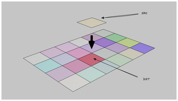
To understand alpha blending, we need to grasp two concepts that can be initially confusing: blend source and blend destination. The blend source refers to the output from the fragment shader, while the blend destination is the existing content in the framebuffer. Additionally, there may be a blend constant, which is a specified constant value.
We can assign different blending behaviors to the alpha channel and the color channel. For a configuration, we need to specify three things: an operation, a srcFactor, and a dstFactor. The final color or alpha can be obtained by:
\begin{aligned}
f_{sc} * C_s \bigodot f_{dc} * C_d &= C \\
f_{sa} * A_s \bigodot f_{da} * A_d &= A \\
\end{aligned}
where f_{sc} and f_{sa} are srcFactors we defined for color and alpha channels and f_{dc} and f_{da} are the dstFactors, and \bigodot is an operation.
Let's explore some common alpha blending formulas used in real-time computer graphics, focusing on their applications and effects.
Additive blending mimics how colors combine in light, resulting in a brighter outcome as two colors are merged. This process closely resembles how our monitors create colors by combining red, green, and blue at varying intensities. In 3D rendering, additive blending often finds application in effects like light emission in particles or creating a glow effect. The equation S + D represents this blending mode, where S denotes the source color and alpha, and D represents the destination.
Multiplicative blending simulates the interaction of light with absorbing mediums or filters. This operation tends to darken colors, making it useful for preserving dark areas such as shadows. The printing industry employs a similar principle, adding colors in multiple passes to achieve darker hues. The equation S * D encapsulates multiplicative blending.
Interpolative blending, true to its name, blends between two colors based on alpha values. This technique proves invaluable when placing a semi-transparent foreground over a background or simulating tinted glass. The source alpha controls the foreground's visibility, and unlike other modes, the order of object drawing significantly impacts the result. To achieve accurate results, it's crucial to draw the furthest objects first, followed by closer ones. The equation A_s * S + (1 - A_s) * D defines interpolative blending.
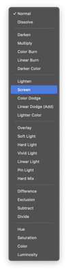
These examples merely scratch the surface of blending effects. To gain a deeper understanding and visual intuition, consider experimenting with image editing software like Photoshop, where you can apply various blend modes to layers.
Going back to the text rendering problem, focusing on achieving a seamless blend of a text-containing texture map over a background. This scenario aligns perfectly with interpolative blending. However, the implementation reveals an unexpected result.

As we observe in the resulting image, dark edges appear around the characters, detracting from our goal of pure white text on a red background. These dark edges are a common artifact encountered when dealing with alpha blending in combination with interpolation.
In our example, we configured the texture sampler to use linear interpolation:
const sampler = device.createSampler({
    addressModeU: 'repeat',
    addressModeV: 'repeat',
    magFilter: 'linear',
    minFilter: 'linear',
    mipmapFilter: 'linear',
});
While this configuration is essential for achieving anti-aliasing, it introduces an unintended side effect. Recall that when generating the text texture, we cleared the canvas using ctx.clearRect(0, 0, width, height);. This function clears the canvas with a transparent black color (0,0,0,0). In contrast, we use opaque white (1,1,1,1) when drawing the text.
The issue arises during the GPU's texture sampling process with linear interpolation. Any sample position between a transparent black pixel and an opaque white pixel can result in a gray pixel, for instance (0.5,0.5,0.5,0.5). This effect is particularly noticeable near the edges of the text. As we know, (0.5,0.5,0.5) represents a gray color, explaining the darker rendering at the text edges.
This outcome contradicts our intention. We aim for the text to gradually transition to the background without altering the text's color itself. The challenge lies in preserving the crisp white color of the text while still achieving smooth edges through alpha blending.
This issue is indeed common and extends beyond our current scenario. Another less obvious situation arises when combining mipmapping with semi-transparent textures, as mipmapping also employs linear interpolation between image layers.
One solution to this problem involves using the same text color for the background, but setting the alpha channel to zero. This approach ensures that interpolation doesn't alter the text color, maintaining its integrity throughout the blending process.
An alternative and more sophisticated solution is to implement premultiplied alpha blending. In this technique, all color values are multiplied by the alpha value before blending. For instance, if an original color is (1.0,1.0,1.0,0.5), its premultiplied version becomes (0.5,0.5,0.5,0.5). This transformation changes how we interpret colors, particularly those with zero alpha. A premultiplied color of (0,0,0,0) can no longer be interpreted as black, as all RGB colors in their premultiplied form become (0,0,0) when the alpha channel is zero.
To address the artifact in our text rendering, we can treat the text texture map as premultiplied. This allows us to interpret the background color (0,0,0,0) as transparent white, rather than transparent black. However, this approach necessitates a different blending formula. Since the foreground color is premultiplied, we no longer need to multiply by the alpha channel during blending. Instead, we use a value of one for the source factor.
C_s + (1-A_s) * C_d = C
Now, let's examine the result of our improved blending approach:
there are few materials online that offer an in-depth mathematical analysis of dark edge artifacts. I found this article very useful, I highly recommend reading the article.