1.16 Lighting
In this section, we'll explore the most fundamental lighting algorithm in computer graphics. It's important to note that, like cameras, there is no direct concept of lighting within the GPU pipeline. The responsibility for lighting calculations falls to us, the developers. Lighting remains one of the oldest and most extensively studied topics in computer graphics, with ongoing developments continually pushing the boundaries of what's possible.
Every lighting solution involves a delicate balance between image quality and rendering speed. Historically, rendering methods were divided into two distinct categories: offline and real-time. Offline rendering aimed for the highest possible image quality and was often employed in movie production, where rendering could take considerable time using large computer clusters. On the other hand, real-time lighting prioritized responsiveness in rendering while sacrificing some visual quality. This approach has been the cornerstone of games and interactive applications.
In recent years, the increasing power of GPUs has blurred the lines between these two categories. Video games have evolved to become cinematic and highly realistic, adopting technologies that were once the exclusive domain of the movie industry.
For this tutorial, we will implement a simple yet performant lighting method known as Phong shading. This technique has become the most widely used lighting solution, making it the default choice for many applications. We'll break down this tutorial into two parts: per-vertex lighting and per-fragment lighting.
Per-vertex lighting calculates lighting effects at each vertex and interpolates the resulting colors across the triangles to simulate the effects on the entire surface. This approach is highly efficient because it calculates lighting sparsely on vertices. However, it may produce less accurate results on models with low polygon counts.
The second solution, per-fragment lighting, takes a different approach. Instead of only calculating lighting at vertices, we interpolate the vertex normals and calculate lighting during the fragment shader stage. This method yields better results with smoother surfaces, as it provides more accurate normals crucial for correct lighting calculations. The trade-off is that it requires more computational power than per-vertex lighting.
Phong Shading Theory
The Phong reflection model, developed by Bui Tuong Phong, is designed to simulate a wide range of lighting effects while maintaining real-time performance. This model has become a cornerstone in computer graphics due to its balance of visual quality and computational efficiency.
At its core, the Phong lighting model breaks down light interaction into three distinct components: ambient, diffuse, and specular.
The ambient component simulates environmental illumination, providing a baseline of light that illuminates all surfaces uniformly, regardless of their orientation. This prevents objects from appearing unnaturally dark in areas not directly lit by a light source.
The diffuse component replicates the light interaction with rough, matte surfaces. It's calculated using the incoming light direction and the surface normal, simulating how light scatters on uneven surfaces. This component is view-independent, meaning it appears the same regardless of the viewer's position.
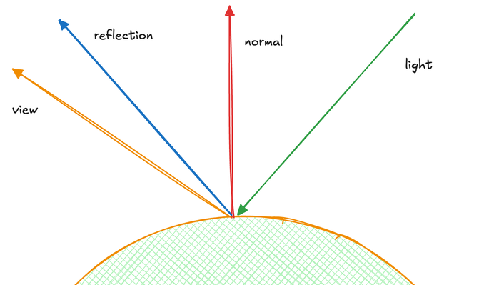
The specular component models the behavior of light on reflective surfaces. Its intensity is determined by the relationship between the reflection direction and the view direction. This creates highlight spots on the surface, with the intensity controlled by a shininess value. Unlike the diffuse component, specular lighting is highly dependent on the viewer's angle, with small changes in viewing position potentially causing significant shifts in the specular highlight.
The Phong shading equation can be summarized as follows:
I = k_a*i_a + k_d * (L \dot N) * i_d + k_s * (R \dot V)^\alpha
In this equation:
k_a,k_d, andk_sare the weights of the ambient, diffuse, and specular components respectively.i_arepresents the constant ambient light.i_dis the diffuse light constant.Lis the light direction vector.Nis the surface normal vector.Ris the reflection direction vector.Vis the viewing direction vector.\alphais the shininess factor, determining the material's reflectivity. Higher values result in smaller, more focused specular highlights, simulating smoother, more mirror-like surfaces. Lower values produce larger specular areas, approximating rougher, more diffuse materials.
Per-vertex lighting
For this tutorial, we will simplify the lighting equation to support a single light source. In a complete Phong shading model, multiple light sources are typically handled by summing up the contributions from each light source. This simplification allows us to focus on the core concepts without overwhelming complexity.
Launch Playground - 1_16_1_lightingLet's examine the key shader changes:
@group(0) @binding(3)
var<uniform> lightDirection: vec3<f32>;
@group(0) @binding(4)
var<uniform> viewDirection: vec3<f32>;
We introduce two new uniform variables: lightDirection and viewDirection. For simplicity, we assume the light source is positioned at the same location as the camera, making these directions identical. In a more complex scenario, these would often differ.
const ambientColor:vec4<f32> = vec4<f32>(0.15, 0.0, 0.0, 1.0);
const diffuseColor:vec4<f32> = vec4<f32>(0.25, 0.25, 0.25, 1.0);
const specularColor:vec4<f32> = vec4<f32>(1.0, 1.0, 1.0, 1.0);

const shininess:f32 = 20.0;
Following the new uniforms, we define constants for material properties. ambientColor, diffuseColor, and specularColor represent the material's response to light. The shininess value controls the size and intensity of specular highlights, with higher values resulting in smaller, more focused highlights.
const diffuseConstant:f32 = 1.0;
const specularConstant:f32 = 1.0;
const ambientConstant: f32 = 1.0;
We also define three constants: diffuseConstant, specularConstant, and ambientConstant. These constants allow us to adjust the strength of each lighting component. Currently set to 1.0, they can be modified to fine-tune the lighting effect.
To modularize our code and improve readability, we create two functions to encapsulate the calculations for specular and diffuse lighting. Let's examine the specular lighting function:
The specular component is calculated using the following equation:
S = (R \dot V)^\alpha
Where:
R is the reflection direction
V is the view direction
\alpha is the shininess factor
This equation is implemented in the following function:
fn specular(lightDir:vec3<f32>, viewDir:vec3<f32>, normal:vec3<f32>,  specularColor:vec3<f32>,
     shininess:f32) -> vec3<f32> {
    var reflectDir:vec3<f32> = reflect(-lightDir, normal);
    var specDot:f32 = max(dot(reflectDir, viewDir), 0.0);
    return pow(specDot, shininess) * specularColor;
}
The specular function calculates the specular component of the Phong lighting model. It takes into account the light direction, view direction, surface normal, specular color, and shininess. The function first computes the reflection direction using WebGPU's built-in reflect() function, which simplifies our code. Then, it calculates the intensity of the reflection by taking the dot product of the reflection direction and view direction, clamped to non-negative values. Finally, it applies the shininess factor to control the size and intensity of the specular highlight.
fn diffuse(lightDir:vec3<f32>, normal:vec3<f32>,  diffuseColor:vec3<f32>) -> vec3<f32>{
    return max(dot(lightDir, normal), 0.0) * diffuseColor;
}
The diffuse function implements the diffuse component of the Phong model, following the equation:
D = (L \dot N) * i_d
Where L is the light direction, N is the surface normal, and i_d is the diffuse color. The dot product of L and N determines how directly the light hits the surface, with the max function ensuring we don't get negative light values.
@vertex
fn vs_main(
    @location(0) inPos: vec3<f32>,
    @location(1) inNormal: vec3<f32>
) -> VertexOutput {

    var n:vec3<f32> = normalize((normalMatrix * vec4<f32>(inNormal, 0.0)).xyz);
    var viewDir:vec3<f32> = normalize((normalMatrix * vec4<f32>(-viewDirection, 0.0)).xyz);
    var lightDir:vec3<f32> = normalize((normalMatrix * vec4<f32>(-lightDirection, 0.0)).xyz);

    var radiance:vec3<f32>  = ambientColor.rgb * ambientConstant +
        diffuse(lightDir, n, diffuseColor.rgb)* diffuseConstant +
        specular(lightDir, viewDir, n, specularColor.rgb, shininess) * specularConstant;

    var out: VertexOutput;
    out.clip_position = projection * modelView * vec4<f32>(inPos, 1.0);
    out.color = radiance;
    return out;
}
In the vertex shader vs_main, we perform several crucial steps:
We transform the surface normal, view direction, and light direction using the normalMatrix. This matrix incorporates both model and view transformations, ensuring all vectors are in the same coordinate space. We then normalize these vectors to ensure correct lighting calculations.
The radiance calculation combines the ambient, diffuse, and specular components. Each component is multiplied by its respective constant to allow fine-tuning of the lighting effect.
Finally, we set the vertex output, including the clip position (transformed by projection and modelView matrices) and the calculated radiance color.
It's worth noting that while we perform these calculations in camera space here, it's also valid to calculate lighting in world coordinates.
let lightDirectionBuffer = new Float32Array([-1.0, -1.0, -1.0]);

const lightDirectionUniformBuffer = createGPUBuffer(device, lightDirectionBuffer, GPUBufferUsage.UNIFORM);

const viewDirectionUniformBuffer = createGPUBuffer(device, new Float32Array([-1.0, -1.0, -1.0]), GPUBufferUsage.UNIFORM);
In our JavaScript code, we introduce two new uniform buffers: lightDirectionUniformBuffer and viewDirectionUniformBuffer. These buffers store the direction vectors for the light source and the camera view, respectively.
We initialize both directions to (-1.0, -1.0, -1.0). This choice assumes that both the light source and the camera are positioned at (3, 3, 3) in world space, pointing towards the origin. The negative values represent the direction from this position towards the center of our scene.
It's important to note that in a more complex scene, these directions might differ and could be dynamically updated based on camera movement or changing light positions.
let uniformBindGroupLayout = device.createBindGroupLayout({
    entries: [
        {
            binding: 0,
            visibility: GPUShaderStage.VERTEX,
            buffer: {}
        },
        {
            binding: 1,
            visibility: GPUShaderStage.VERTEX,
            buffer: {}
        },
        {
            binding: 2,
            visibility: GPUShaderStage.VERTEX,
            buffer: {}
        },
        {
            binding: 3,
            visibility: GPUShaderStage.VERTEX,
            buffer: {}
        },
        {
            binding: 4,
            visibility: GPUShaderStage.VERTEX,
            buffer: {}
        }
    ]
});

let uniformBindGroup = device.createBindGroup({
    layout: uniformBindGroupLayout,
    entries: [
        {
            binding: 0,
            resource: {
                buffer: modelViewMatrixUniformBuffer
            }
        },
        {
            binding: 1,
            resource: {
                buffer: projectionMatrixUniformBuffer
            }
        },
        {
            binding: 2,
            resource: {
                buffer: normalMatrixUniformBuffer
            }
        },
        {
            binding: 3,
            resource: {
                buffer: lightDirectionUniformBuffer
            }
        },
        {
            binding: 4,
            resource: {
                buffer: viewDirectionUniformBuffer
            }
        }
    ]
});
To incorporate these new uniforms into our rendering pipeline, we need to update our GPU binding configurations. Similarly, in the uniformBindGroup, we create corresponding entries that link these bindings to our newly created uniform buffers.
Per-fragment lighting
Let's now explore the transition from per-vertex to per-fragment shading, a technique that significantly improves the visual quality of our rendered scenes.
Launch Playground - 1_16_2_lightingIn our previous per-vertex approach, we calculated lighting effects at each vertex and then interpolated these results across the triangle's surface. While computationally efficient, this method introduced noticeable flatness artifacts, especially on curved surfaces represented by low-polygon models.
Per-fragment shading takes a different approach. Instead of computing final lighting at vertices, we pass the view direction, light direction, and surface normal to the fragment shader stage. We interpolate only the surface normal across the triangle, rather than interpolating the final color. Lighting calculations are then performed for each fragment, using the interpolated normal.
This method improves the representation of curvature. While triangles are inherently flat, they often approximate curved surfaces. Per-vertex lighting treats all triangles as truly flat, losing the illusion of curvature. Per-fragment shading, by interpolating normals, better preserves the appearance of smooth, curved surfaces.
It's important to understand that while this method provides a more accurate approximation, it's still an approximation. The interpolated normals are not the true normals of the surface at every point, but they offer a significant improvement over the flat shading of per-vertex lighting.
This technique does come with a performance cost, as we're now performing lighting calculations for each fragment rather than for each vertex. However, the visual improvement is often worth the additional computational expense, especially on modern hardware.
In the following sections, we'll dive into the implementation details of per-fragment shading.
@vertex
fn vs_main(
    @location(0) inPos: vec3<f32>,
    @location(1) inNormal: vec3<f32>
) -> VertexOutput {
    var out: VertexOutput;

    out.viewDir = normalize((normalMatrix * vec4<f32>(-viewDirection, 0.0)).xyz);
    out.lightDir = normalize((normalMatrix * vec4<f32>(-lightDirection, 0.0)).xyz);
    out.normal = normalize(normalMatrix * vec4<f32>(inNormal, 0.0)).xyz;

    out.clip_position = projection * modelView * vec4<f32>(inPos, 1.0);
    return out;
}
Let's examine the shader code changes that facilitate the transition to per-fragment shading. We're retaining the same logic for calculating each lighting channel, but the vertex shader now serves a different purpose. Instead of computing the final lighting at the vertex level, it focuses on passing the view direction and light direction to the fragment shader.
@fragment
fn fs_main(in: VertexOutput) -> @location(0) vec4<f32> {

    var lightDir:vec3<f32> = in.lightDir;
    var n:vec3<f32> = normalize(in.normal);
    var viewDir: vec3<f32> = in.viewDir;

    var radiance:vec3<f32>  = ambientColor.rgb * ambientConstant +
        diffuse(lightDir, n, diffuseColor.rgb)* diffuseConstant +
        specular(lightDir, viewDir, n, specularColor.rgb, shininess) * specularConstant;

    return vec4<f32>(radiance ,1.0);
}
In the fragment shader stage, it's crucial to normalize the interpolated normals. Interpolation can affect the length of these normals, and for precise lighting calculations, they must be normalized. However, this normalization isn't required for the light and view directions, as their values remain consistent across all vertices.
With normalized normals and stable light and view directions, we proceed to calculate the radiance in the fragment shader, which serves as the output color.
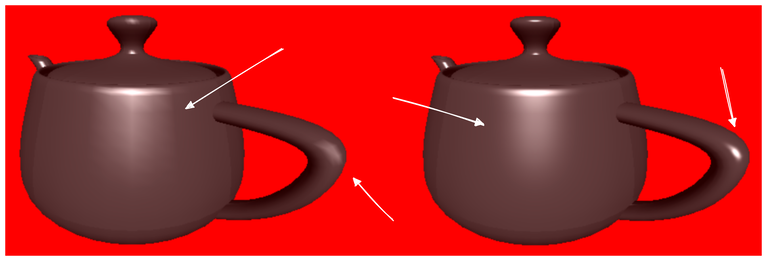
With per-fragment lighting, we can observe a significant improvement in the surface's smoothness.