5.5 Transparency with Depth Peeling
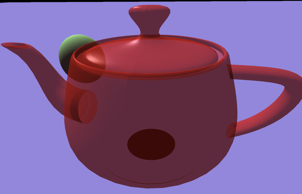
Transparency is another fundamental visual effect not supported by 3D graphics APIs out of the box, and its implementation is not trivial. Previously, I introduced alpha blending and used it to achieve certain semi-transparent effects, such as when rendering text. However, when it comes to 3D objects, alpha blending alone will not yield the correct result.
Launch Playground - 5_05_transparencyThe fundamental issue is that depth testing is required to implement occlusion, but it conflicts with transparency rendering. Imagine a 3D scene with both opaque and transparent objects. If we disable depth testing, occlusion will not be rendered properly. However, if we enable depth testing, transparent objects in front of opaque objects will occlude the opaque objects. The correct rendering should allow transparent objects to overlay the opaque ones, allowing us to see through the transparent objects to the opaque ones behind them.
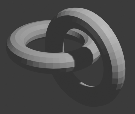
One naive idea is to draw the scene's objects in order from back to front, with depth testing applied only to each individual object, and turned off when overlaying objects on top of others. If you have used Photoshop before, this is similar to the concept of layers. The problem is that in certain situations, it's difficult to order objects. For example:
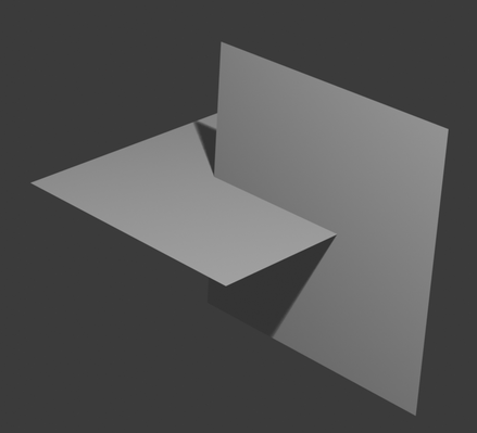
If ordering objects is not a good solution, you might consider ordering the triangles. However, like ordering objects, determining the order of triangles can be difficult. For example:
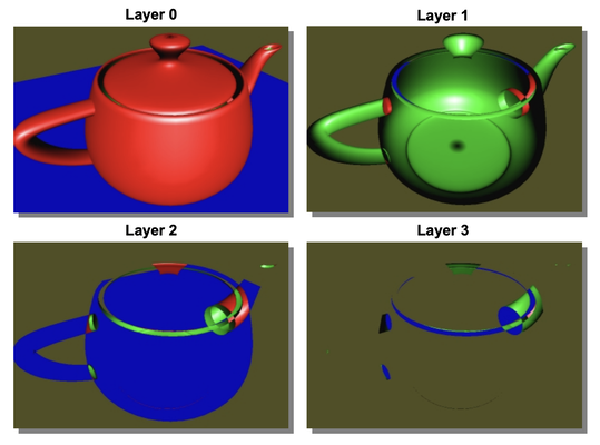
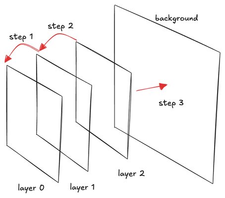
In this tutorial, we will explore a better technique called depth peeling. The idea is similar to Photoshop's layers, but instead of treating objects or triangles as layers, we peel the scene from the front to the back, placing each peeled scene as a layer and composing them together to form the final rendering.
Let me explain what I mean by peeling the scene. First, we render the scene with depth testing. This will render the front-most objects regardless of transparency. At the same time, we keep the depth map. The rendering result will be Layer Zero. Then, we render the scene again, but only render fragments that are behind the first depth map, i.e., the depth is larger than the initial depth value. The result is that we have peeled away the front-most fragments and revealed the second layer of fragments, which we call Layer One. Similarly, we keep this new depth map. From now on, we repeat the procedure, rendering the scene again and keeping fragments only when their depth value is larger than the current depth map. This will be Layer Two, and so on.
In the end, we will break down the scene into a set of layers based on depth. In the final pass, we compose the layers from front to back using alpha blending to create the final result.
The key concept of depth peeling is not difficult. One crucial aspect of understanding it thoroughly is grasping the alpha blending formula used for front-to-back blending.
I have worked in the field of computer graphics for many years, but I must admit, I found alpha blending and concepts like premultiplied alpha, back-to-front blending, and front-to-back blending confusing. While it's easy to find online resources that provide the formulas for different situations, truly understanding the underlying principles is crucial for handling more complex cases.
I want to express my gratitude to the book Advanced Graphics Programming Using OpenGL, which features a dedicated chapter that patiently explains how alpha blending works (starting on page 185).
My earlier confusion stemmed from conceptualizing alpha as opacity, similar to how we perceive transparency in real life. For example, imagining a semi-transparent red film, where red is the color and alpha represents the semi-transparency. This misconception made it difficult for me to grasp concepts like premultiplied alpha. In real life, an object's color is generally unrelated to its transparency – a very transparent red film should still appear red. However, in computer graphics, we have the concept of premultiplied alpha, where we multiply the alpha value with the color, causing a very transparent red to appear dark red or even black.
The correct way to conceptualize alpha is as the "amount of color" rather than opacity. In computer graphics, there is no true transparency; it's more akin to painting, where all pigments are fully opaque, differing only in color.
To create the illusion of semi-transparency, we must mix colors by taking a weighted average of existing colors, simulating the effect of light passing through multiple layers of color. When mixing colors, the only controllable factor is the amount of color, which corresponds to the alpha channel of an RGBA pixel.
Thus, the most basic form of alpha blending between two colors is:
\begin{aligned}
C_{new} &= C_{src} * A_{src} + C_{dst} * (1 - A_{src}) \\
A_{new} &= 1.0
\end{aligned}
This describes a typical weighted average of two colors, assuming both colors and the resulting color
C_{new} are fully opaque. In this case, only C_{src} has an alpha value and is used in the formula, while C_{dst} and C_{new} have an alpha of 1.0 (full opacity). If C_{src} is the foreground color, the formula determines how much of the foreground color will be visible, without actual transparency involved.
We can think of each pixel as a small color bucket, where the amount of color poured into a single bucket cannot exceed 1.0 (i.e., no overflow).
When mixing two colors, we can imagine all pixel buckets initially containing the background color
C_{dst} at full opacity (1.0). To make room for adding the foreground color with an alpha value A_{src}, we need to remove some of the existing color. To ensure the resulting bucket remains full, the amount to remove should be 1.0−A_{src}.
When blending more than two colors additively, we must adjust the formula because we cannot assume that the resulting color at each step has no alpha (i.e., always a full bucket).
As we add colors to this bucket, we must account for the amount of color already present. This is why it is necessary to keep track of the current color amount in the bucket.
Let's label the colors to be blended as C_1, C_2, C_3, and so on. The formula for blending multiple colors becomes:
\begin{aligned}
C_{new} &= C_1 * A_1 + C_2 * A_2 * (1.0 - A_1) \\
A_{new} &= A_1 + A_2 * (1.0 - A_1)
\end{aligned}
The weighted average of the two colors remains the same, but now we multiply C_2 by its alpha A_2 because C_2 is not fully opaque.
The new alpha formula, A_{new} = A_1 + A_2 * (1.0−A_1), ensures that the new alpha never exceeds 1.0, preventing overflow.
At first glance, the common equations for front-to-back alpha blending found online might not seem to match the above formula. However, they are actually equivalent. In front-to-back alpha blending, the destination color is the foreground, and the source is the background. The following formula uses
A_{dst} to store the (1.0−A_1) term from the above equation. By substituting C_{src} and A_{src} with C_2 and A_2, and C_{dst} and A_{dst} with C_1 and (1.0−A_1), we obtain the same equation:
\begin{aligned}
C_{dst} &= A_{dst} * (A_{src} * C_{src}) + C_{dst} \\
A_{dst} &= (1 - A_{src}) * A_{dst}
\end{aligned}
Now that we have clarified the blending equation, let's look at the implementation:
@group(0) @binding(0)
var<uniform> modelView: mat4x4<f32>;
@group(0) @binding(1)
var<uniform> projection: mat4x4<f32>;
@group(0) @binding(2)
var<uniform> normalMatrix: mat4x4<f32>;
@group(0) @binding(3)
var<uniform> lightDirection: vec3<f32>;
@group(0) @binding(4)
var<uniform> viewDirection: vec3<f32>;

@group(1) @binding(0)
var<uniform> offset: vec3<f32>;
@group(1) @binding(1)
var<uniform> ambientColor:vec4<f32>;// = vec4<f32>(0.15, 0.10, 0.10, 1.0);
@group(1) @binding(2)
var<uniform> diffuseColor:vec4<f32>;// = vec4<f32>(0.55, 0.55, 0.55, 1.0);
@group(1) @binding(3)
var<uniform> specularColor:vec4<f32>;// = vec4<f32>(1.0, 1.0, 1.0, 1.0);

@group(1) @binding(4)
var<uniform> shininess:f32;// = 20.0;

const diffuseConstant:f32 = 1.0;
const specularConstant:f32 = 1.0;
const ambientConstant: f32 = 1.0;

fn specular(lightDir:vec3<f32>, viewDir:vec3<f32>, normal:vec3<f32>,  specularColor:vec3<f32>,
     shininess:f32) -> vec3<f32> {
    let reflectDir:vec3<f32> = reflect(-lightDir, normal);
    let specDot:f32 = max(dot(reflectDir, viewDir), 0.0);
    return pow(specDot, shininess) * specularColor;
}

fn diffuse(lightDir:vec3<f32>, normal:vec3<f32>,  diffuseColor:vec3<f32>) -> vec3<f32>{
    return max(dot(lightDir, normal), 0.0) * diffuseColor;
}

struct VertexOutput {
    @builtin(position) clip_position: vec4<f32>,
    @location(0) viewDir: vec3<f32>,
    @location(1) normal: vec3<f32>,
    @location(2) lightDir: vec3<f32>,
    @location(3) inPos: vec4<f32>,
};

@vertex
fn vs_main(
    @location(0) inPos: vec3<f32>,
    @location(1) inNormal: vec3<f32>
) -> VertexOutput {
    var out: VertexOutput;

    out.viewDir = normalize((normalMatrix * vec4<f32>(-viewDirection, 0.0)).xyz);
    out.lightDir = normalize((normalMatrix * vec4<f32>(-lightDirection, 0.0)).xyz);
    out.normal = normalize(normalMatrix * vec4<f32>(inNormal, 0.0)).xyz;
    var wldLoc:vec4<f32> = modelView * vec4<f32>(inPos+offset, 1.0);
    out.clip_position = projection * wldLoc;
    out.inPos = projection * wldLoc;
    return out;
}

@group(2) @binding(0)
var t_depth: texture_depth_2d;
@group(2) @binding(1)
var s_depth: sampler_comparison;
@group(2)
@binding(2)
var<storage,read_write> debug: vec4<f32>;

@fragment
fn fs_main(in: VertexOutput,  @builtin(front_facing) face: bool) -> @location(0) vec4<f32> {
    var uv:vec2<f32> = 0.5*(in.inPos.xy/in.inPos.w + vec2(1.0,1.0));
    var visibility:f32 = textureSampleCompare(
        t_depth, s_depth,
        vec2(uv.x, 1.0-uv.y),  in.clip_position.z - 0.0001
    );

    debug = in.clip_position;
    //debug = in.inPos;
    //debug = vec4(uv,in.inPos.z/in.inPos.w, in.clip_position.z);
    if (visibility < 0.5) {
        discard;
    }

    var lightDir:vec3<f32> = normalize(in.lightDir);
    var n:vec3<f32> = normalize(in.normal);

    var color:vec3<f32> = diffuseColor.rgb;

    if (!face) {
        n = normalize(-in.lightDir);
      //  color = vec3<f32>(0.0, 1.0, 0.0);
    }
    var viewDir: vec3<f32> = in.viewDir;

    var radiance:vec3<f32>  = ambientColor.rgb * ambientConstant +
                    diffuse(-lightDir, n, color)* diffuseConstant +
                    specular(-lightDir, viewDir, n, specularColor.rgb, shininess) * specularConstant;
    //return vec4<f32>(uv.xy,0.0,1.0);
    return vec4<f32>(radiance * diffuseColor.w, diffuseColor.w);
}
This shader should look familiar. It is similar to the lighting shader with a minor modification. This shader loads a depth map and compares the current depth value with the value in the depth map. It renders the fragment only when the new depth is greater than the depth in the map, which allows us to peel away objects before the depth map.
out.clip_position = projection * wldLoc;
out.inPos = projection * wldLoc;
var uv:vec2<f32> = 0.5*(in.inPos.xy/in.inPos.w + vec2(1.0,1.0));
var visibility:f32 = textureSampleCompare(
    t_depth, s_depth,
    vec2(uv.x, 1.0-uv.y),  in.clip_position.z - 0.0001
);

debug = in.clip_position;
//debug = in.inPos;
//debug = vec4(uv,in.inPos.z/in.inPos.w, in.clip_position.z);
It’s worth noting the logic used to calculate the UV coordinates for depth map fetching and the current depth. You might find it unusual that I have two variables, clip_position and inPos, both seemingly storing the clip space position vector. They appear to be duplicates.
This is intentional to illustrate that the clip_position variable passed into the vertex shader undergoes changes before reaching the fragment shader. Consequently, when we read it back in the fragment shader, it is not the same clip position, despite having the same variable name.
Recall when we introduced the GPU pipeline, we learned that during the vertex shader stage, we only define properties sparsely for each vertex. Then, during a step called rasterization, we convert triangle geometries into fragments, similar to laying bricks. The values defined at each fragment are obtained through bilinear interpolation. While interpolation explains some of the value changes, it does not account for all of them. Another significant change is that the pipeline alters the coordinate system. For x and y, the pipeline converts from clip space to normalized device coordinates, and then from normalized device coordinates to framebuffer coordinates (where the top-left corner is at (0.0, 0.0), with x increasing to the right and y increasing downward). For z, it is mapped to a value in the viewport depth range: vp.minDepth+n.z×(vp.maxDepth−vp.minDepth).
There is a technical term to describe the values passed into the fragment shader: RasterizationPoint. Keep in mind that despite variable names being the same, there are changes in the data.
With this in mind, understanding the UV calculation should be straightforward. We map the normalized device coordinate (NDC) range from [-1,1] to [0,1] and flip the y-axis because texture coordinates increase downward. For the z value, we simply read it from clip_position.z.
Let's go over how to set up this pipeline.
First, we need an empty canvas to serve as the background. We render from front to back and finally overlay what has been rendered onto the background.
At the start of each round, we need to clear our destination (dst) texture to (0, 0, 0, 1). This is easily accomplished using the built-in functionality for clearing color attachments, without needing to draw anything. The dst texture serves as the layer zero for our front-to-back alpha blending. The first layer will blend with this texture, the second layer will blend with the resulting texture, and so on. Ultimately, the dst texture will contain all layers composed in the front-to-back order, which is then applied to the background.
You might wonder why the dst texture is cleared to (0, 0, 0, 1) rather than (0, 0, 0, 0). Shouldn't layer zero be completely transparent? Indeed, the first layer should be fully transparent and have the color (0, 0, 0, 0). However, in front-to-back blending, we use the alpha channel to store (1.0−A_{dst}) instead of A_{dst} itself. Therefore, we set the alpha to 1.0 here.
const renderPassCleanupDesc = {
    colorAttachments: [{
        view: dstTexture.createView(),
        clearValue: { r: 0, g: 0, b: 0, a: 1 },
        loadOp: 'clear',
        storeOp: 'store'
    }]
}
let passEncoderCleanup = commandEncoder.beginRenderPass(renderPassCleanupDesc);
passEncoderCleanup.setViewport(0, 0, canvas.width, canvas.height, 0, 1);
passEncoderCleanup.end();
For the actual rendering, we define two depth maps for alternating use. During each peeling step, we read depth values from one depth map and write to the other. Since we can't read and write to the same depth map simultaneously, we use two depth maps in an alternating pattern.
depthAttachment0 = {
    view: depthTexture1.createView(),
    depthClearValue: 1,
    depthLoadOp: 'clear',
    depthStoreOp: 'store'
};

depthAttachment1 = {
    view: depthTexture0.createView(),
    depthClearValue: 1,
    depthLoadOp: 'clear',
    depthStoreOp: 'store'
};
let colorAttachment0 = {
    view: colorTextureForDebugging.createView(),
    clearValue: { r: 0, g: 0, b: 0, a: 0 },
    loadOp: 'clear',
    storeOp: 'store'
};

let colorAttachment1 = {
    view: colorTextureForDebugging.createView(),
    clearValue: { r: 0, g: 0, b: 0, a: 0 },
    loadOp: 'clear',
    storeOp: 'store'
};
const renderPassDesc0 = {
    colorAttachments: [colorAttachment0],
    depthStencilAttachment: depthAttachment0
};

const renderPassDesc1 = {
    colorAttachments: [colorAttachment1],
    depthStencilAttachment: depthAttachment1
};
for (let p = 0; p < 6; ++p) {
    let passEncoder0 = null;
    if (p % 2 == 0) {
        passEncoder0 = commandEncoder.beginRenderPass(renderPassDesc0);
    }
    else {
        passEncoder0 = commandEncoder.beginRenderPass(renderPassDesc1);
    }
    passEncoder0.setViewport(0, 0, canvas.width, canvas.height, 0, 1);
    teapot.encode(passEncoder0, pipeline, p);
    plane.encode(passEncoder0, pipeline, p);
    sphere.encode(passEncoder0, pipeline, p);
    passEncoder0.end();
    let passEncoder1 = commandEncoder.beginRenderPass(renderPassBlend);
    passEncoder1.setViewport(0, 0, canvas.width, canvas.height, 0, 1);
    blender.encode(passEncoder1);
    passEncoder1.end();
}
At the beginning, we initialize the depth maps to all ones because one is the maximum possible depth value. This ensures that during the first peeling step, we can render the frontmost layer.
For the color attachment, we always clear it to (0, 0, 0, 0) for front-to-back rendering.
Notice that we loop the peeling step six times. This hardcoded value means we can peel a maximum of six layers. If there are more layers in the scene, our program won’t be able to handle them. This is a limitation of the current implementation, as we must predetermine the maximum number of supported layers.
After rendering the objects, we call the blender to compose the newly rendered layer onto the existing layer. We will explain the blender in detail later.
struct VertexOutput {
    @builtin(position) clip_position: vec4<f32>,
    @location(0) tex_coords: vec2<f32>
};

@vertex
fn vs_main(
    @location(0) inPos: vec4<f32>
) -> VertexOutput {
    var out: VertexOutput;
    out.clip_position = vec4<f32>(inPos.xy, 0.0, 1.0);
    out.tex_coords = inPos.zw;
    return out;
}

// Fragment shader
@group(0) @binding(0)
var t_src: texture_2d<f32>;
@group(0) @binding(1)
var s: sampler;

@fragment
fn fs_main(in: VertexOutput) -> @location(0) vec4<f32> {
    var color:vec4<f32> = textureSample(t_src, s, in.tex_coords);
    return color;
}
The shader is straightforward; it loads a texture (the rendered layer) and applies it to the framebuffer. The crucial part is the alpha blending setup of the pipeline:
const colorState = {
    format: 'bgra8unorm',
    blend: {
        color: {
            operation: "add",
            srcFactor: 'dst-alpha',
            dstFactor: 'one',
        },
        alpha: {
            operation: "add",
            srcFactor: 'zero',
            dstFactor: 'one-minus-src-alpha',
        }
    }
};
Note that this uses the same blending equation explained earlier, assuming that the source color is already premultiplied (see the shader for object rendering).
const renderPassBlend = {
    colorAttachments: [{
        view: dstTexture.createView(),
        clearValue: { r: 0, g: 0, b: 0, a: 0 },
        loadOp: 'load',
        storeOp: 'store'
    }]
}
let passEncoder1 = commandEncoder.beginRenderPass(renderPassBlend);
passEncoder1.setViewport(0, 0, canvas.width, canvas.height, 0, 1);
blender.encode(passEncoder1);
passEncoder1.end();
The above render pass descriptor starts with a cleaned-up destination (dst) texture. Notice that the dst texture was cleared to (0, 0, 0, 1), and from then on, we do not clear the texture anymore. We load it for each blending operation as the texture contains the layers we have already composed.
struct VertexOutput {
    @builtin(position) clip_position: vec4<f32>,
    @location(0) tex_coords: vec2<f32>
};

@vertex
fn vs_main(
    @location(0) inPos: vec4<f32>
) -> VertexOutput {
    var out: VertexOutput;
    out.clip_position = vec4<f32>(inPos.xy, 0.0, 1.0);
    out.tex_coords = inPos.zw;
    return out;
}

// Fragment shader
@group(0) @binding(0)
var t_composed: texture_2d<f32>;
@group(0) @binding(1 )
var s_composed: sampler;

@fragment
fn fs_main(in: VertexOutput) -> @location(0) vec4<f32> {
    return textureSample(t_composed, s_composed, in.tex_coords);
}
const colorState = {
    format: 'bgra8unorm',
    blend: {
        alpha: {
            operation: "add",
            srcFactor: 'one',
            dstFactor: 'one-minus-src-alpha',
        },
        color: {
            operation: "add",
            srcFactor: 'one',
            dstFactor: 'one-minus-src-alpha',
        }
    }
};
let finalEncoder = commandEncoder.beginRenderPass(renderPassFinal);
final.encode(finalEncoder);
finalEncoder.end();
Finally, in the last step, we render the composed layers onto a black background using back-to-front blending. Since our color is premultiplied, we use the C_{src} +(1−A_{src}) \times C_{dst} formula.