5.3 Equirectangular Rendering
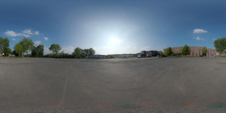
Equirectangular rendering is a technique widely used for displaying 360-degree panorama images. This method is particularly popular in interior design visualizations and for rendering distant backgrounds or skies in games. With the rise of 360 cameras, this technique has gained even more relevance.
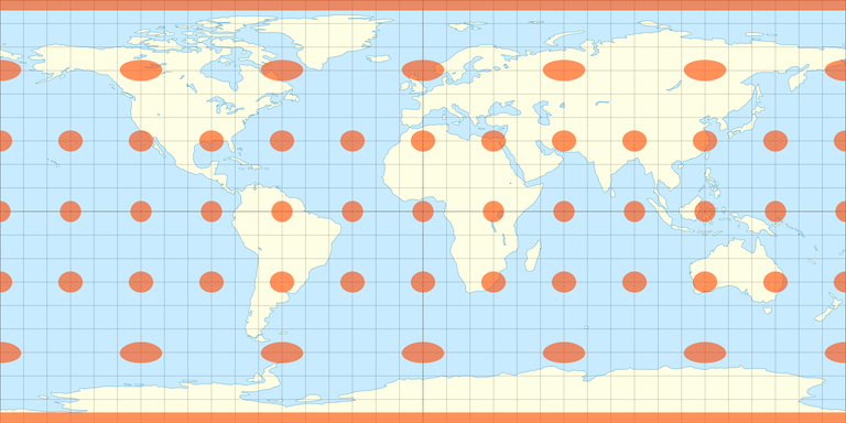
Launch Playground - 5_03_equalrectangle_renderingAn equirectangular texture is essentially a flattened representation of a spherical surface, similar to how a globe is projected onto a 2D map. If you are familiar with this projection, you know that it maps the globe into a rectangular format where longitude and latitude define specific points on the map. This is the basis for accessing the equirectangular texture map through spherical coordinates.
The concept behind equirectangular rendering is straightforward. Typically, texture mapping is done using UV coordinates. In equirectangular rendering, however, we envision an imaginary sphere surrounding the camera. The framebuffer being rendered acts as a plane in front of the camera. For each fragment on this image plane, a ray is cast from the camera position through the fragment, intersecting the imaginary sphere. This intersection point is defined by spherical coordinates, specifically theta and phi.
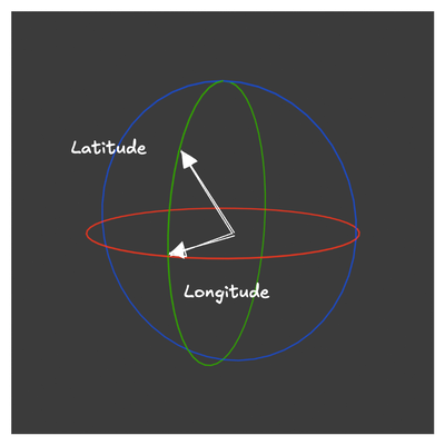
Using these spherical coordinates, we can derive UV texture coordinates to sample the equirectangular texture map. This setup allows for the camera to rotate freely, providing a full 360-degree view of the panorama image.
@group(0) @binding(0)
var<uniform> modelView: mat4x4<f32>;
@group(0) @binding(1)
var<uniform> projection: mat4x4<f32>;

struct VertexOutput {
    @builtin(position) clip_position: vec4<f32>,
    @location(0) worldPos: vec3<f32>
};

@vertex
fn vs_main(
    @location(0) inPos: vec3<f32>
) -> VertexOutput {
    var out: VertexOutput;
    out.worldPos = inPos;
    var wldLoc:vec4<f32> = modelView * vec4<f32>(inPos, 1.0);
    out.clip_position = projection * wldLoc;
    return out;
}

// Fragment shader

const pi:f32 = 3.141592654;
@group(0) @binding(2)
var t_diffuse: texture_2d<f32>;
@group(0) @binding(3)
var s_diffuse: sampler;

@fragment
fn fs_main(in: VertexOutput) -> @location(0) vec4<f32> {
    var n:vec3<f32> = normalize(in.worldPos);

    var len:f32 = sqrt (n.x *n.x + n.y*n.y);

    var s:f32 = acos( n.x / len);
    if (n.y < 0) {
        s = 2.0 * pi - s;
    }

    s = s / (2.0 * pi);
    var tex_coord:vec2<f32> = vec2(s , ((asin(n.z) * -2.0 / pi ) + 1.0) * 0.5);
    return textureSampleLevel(t_diffuse, s_diffuse, tex_coord, 0);
}
Let's now examine the shader code used for equirectangular rendering. The vertex shader performs standard model-view and projection transformations, and it also passes world coordinates to the fragment shader. These world coordinates are essential for deriving spherical coordinates used to sample the equirectangular texture map.
In the fragment shader, we start by retrieving the world coordinates. We then calculate the longitude and latitude. The longitude is derived from:
var n:vec3<f32> = normalize(in.worldPos);

var len:f32 = sqrt (n.x *n.x + n.y*n.y);

var s:f32 = acos( n.x / len);
and the latitude from:
if (n.y < 0) {
    s = 2.0 * pi - s;
}

s = s / (2.0 * pi);
Since latitude ranges from -π to π, we scale it to the range of 0 to 1. Additionally, we flip the latitude or V coordinate, as the texture coordinate system and the spherical coordinate system have opposite orientations along V or latitude.
Texture sampling is performed as usual after these calculations.
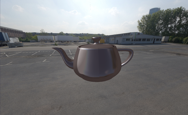
Equirectangular rendering is also highly effective for rendering reflective surfaces like metal, mirrors, or glass. These surfaces reflect their surrounding environment, and equirectangular textures can be used to capture this reflection. Here’s how you can implement this:
let nn:vec3<f32> = reflect(-viewDir, n);

var len:f32 = sqrt (nn.x *nn.x + nn.y*nn.y);
var s:f32 = acos( nn.x / len);
if (nn.y < 0) {
    s = 2.0 * pi - s;
}
s = s / (2.0 * pi);
var tex_coord:vec2<f32> = vec2(s , ((asin(nn.z) * -2.0 / pi ) + 1.0) * 0.5);
var diffuseColor:vec4<f32> =
        textureSampleLevel(t_diffuse, s_diffuse, tex_coord, 0);
In this code snippet, we first compute the reflection direction based on the surface normal and viewing direction. The longitude (s) and latitude are derived from this reflection vector. The latitude is scaled to fit the texture coordinate system. We then sample the diffuse color from the equirectangular texture using these coordinates.
In contrast to our previous shadow map demo, where a fixed color was used, here we sample the diffuse color from the surrounding environment represented by the equirectangular texture. The process remains similar to the shadow map example, so we’ll skip the detailed explanation.
Here is the output of the above example: