5.4 Mega Texture
Mega textures, also known as virtualized textures, are inspired by the concept of virtualization in computer science, such as virtual memory. Virtual memory allows applications to use more memory than is physically available by dynamically loading only the necessary portions. Similarly, virtualized textures enable the management of textures that exceed the video memory capacity.
Launch Playground - 5_04_mega_textureTo understand the significance, consider the size of image data. For instance, a 1024x1024 RGBA image occupies 4MB in video memory. A video card with 8GB of memory can hold a maximum of 2000 such images. However, since video memory must be shared with other resources, the actual number of texture maps is even more limited. In large game scenes, this limitation can be easily exhausted.
Additionally, there is a maximum size for a single texture map. According to the WebGPU specification, this can be queried by maxTextureDimension2D for 2D textures, with a default value of 8192. If you have a single image larger than this size, you will need techniques like mega textures.
Moreover, we don’t always need to load the highest resolution version of a texture. When a textured surface is viewed from afar, a lower-resolution version suffices to resolve sampling issues. This concept is addressed by mipmaps. However, naively using mipmaps increases memory usage, as the original image and a pyramid of lower-resolution images are loaded into memory.
Mega textures allow working with a large pool of texture maps whose combined size exceeds video memory capacity. The process involves two passes. During the first pass, instead of using the actual texture maps, a pre-rendering step determines which textures should be visible and at what level of detail. The CPU then assembles a single texture map by tiling the visible textures and establishes a lookup table. This table allows locating the corresponding tile on the assembled texture based on texture ID and detail level. In the second rendering pass, texture visibility is recalculated, and the lookup table is used to sample the appropriate tile.
This approach removes the limitation on the overall number of texture maps, as long as the assembled texture map can hold the maximum number of visible textures.
The assembled texture map should be managed like a cache. If a tile is already present, it should not be reloaded, and its entry in the lookup table should not be updated. If the assembled texture map is full, the least-used tile is replaced. The goal is to minimize updates to the assembled texture map.
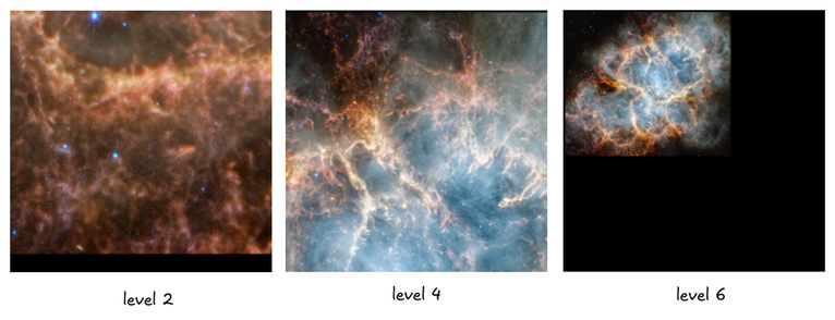
In this example, we explore a simplified case of mega textures. We render a screen-aligned plane to display a large texture, such as the Crab Nebula captured by the James Webb Space Telescope. The raw image size is 10752x9216, occupying 129.3MB, which is too large to load in a single texture map. Although this is a special case, mega textures can be applied to more general scenarios where surfaces are not aligned with the screen. This demo also illustrates large image loading and navigation, similar to Google Maps.
Since the original image is too large, we don’t load it all at once. Instead, we use a preprocessing program to divide it into 256x256 tiles. To achieve different levels of detail, the preprocessor also creates coarse versions of the image, maintaining all tiles at 256x256 for simplicity. For instance, four 256x256 tiles form a single 512x512 tile, which is then downscaled to 256x256 for a coarser level.
Here is the code for the tile preprocessor in Python:
import PIL.Image
import math
image = PIL.Image.open('crab_nebula.png')
# Round the image width and height to multiples of 256.
image = image.crop((0, 0, math.ceil(image.width/256)*256,math.ceil(image.height/ 256)*256))
# Add a 2-pixel padding on tile edges.
padding = 2
# Each level halve the width/height,
# hence we need log(256) levels to shrink a tile into a single pixel.
for lv in range(0,math.floor(math.log(256,2))+1):
    # How much we need to resize the original image for this level.
    resize_ratio = math.pow(2, lv)
    scaled_width = int(image.width / resize_ratio)
    scaled_height = int(image.height / resize_ratio)
    resized_image = image.resize((scaled_width, scaled_height))
    # h,v are the horizontal and vertical tile counts.
    h = math.ceil(scaled_width / 256)
    v = math.ceil(scaled_height / 256)
    for y in range(0,v):
        for x in range(0,h):
            # Crop a tile, the size of a tile is 260x260 including the padding.
            cropped_image = resized_image.crop((x*256-padding, y*256-padding, (x+1)*256+padding,(y+1)* 256+padding))
            # Save the tile into a png file.
            cropped_image.save('../crab_nebula/crab_'+str(lv)+'_'+str(y)+'_'+str(x)+'.png')
Notice that, for easy loading in the code, we name our tiles using the pattern crab_<level>_<index y>_<index x>. Here, level denotes the detail level, y is the vertical index of all tiles at the same level, and x is the horizontal index.
Additionally, a padding has been added to all tiles, making the actual size 4 pixels larger than 256 along each dimension. The necessity of this padding will be explained later.
First, let's configure some constants. Here is the relevant code:
const imageWidth = 10752;
const imageHeight = 9216;
const tileSizeWithoutPadding = 256;
const textureSizeWithoutPadding = 2048;
const padding = 2;
const maxVisibleTileCountOnTexture = textureSizeWithoutPadding * textureSizeWithoutPadding / (tileSizeWithoutPadding * tileSizeWithoutPadding);
const levelCount = Math.log2(tileSizeWithoutPadding) + 1;

const tileH = Math.ceil(imageWidth / tileSizeWithoutPadding);
const tileV = Math.ceil(imageHeight / tileSizeWithoutPadding);

let levelTileCount = [];
for (let l = 0; l < levelCount; ++l) {
    const leveltileSizeWithoutPadding = tileSizeWithoutPadding * Math.pow(2, l);

    const levelTileH = Math.ceil(imageWidth / leveltileSizeWithoutPadding);
    const levelTileV = Math.ceil(imageHeight / leveltileSizeWithoutPadding);

    levelTileCount.push(...[levelTileH, levelTileV, leveltileSizeWithoutPadding, 0]);
}

let overallTileCount = 0;

for (let i = 0; i < levelCount; ++i) {
    overallTileCount += levelTileCount[i * 4] * levelTileCount[i * 4 + 1];
}
In this setup, imageWidth and imageHeight hardcode the raw image size. textureSizeWithoutPadding holds the texture map we will use to store visible tiles. maxVisibleTileCountOnTexture is the maximum possible number of visible tiles, limited by the size of the texture map.
levelCount is the total number of levels, which is the count needed to halve a tile of size 256 down to a single pixel. tileH and tileV are the horizontal and vertical tile counts on the raw image.
levelTileCount is an array recording the horizontal and vertical tile counts for all levels, along with each level's tile size on the original image. overallTileCount is the sum of the tile counts for all levels.
function keyToLevel(key) {
    let keyRemain = key;
    let level = 0;

    while (keyRemain >= levelTileCount[level * 4] * levelTileCount[level * 4 + 1]) {
        keyRemain -= levelTileCount[level * 4] * levelTileCount[level * 4 + 1];
        level += 1;
    }

    return { level, tileH: levelTileCount[level * 4], tileV: levelTileCount[level * 4 + 1], tileSizeWithoutPadding: levelTileCount[level * 4 + 2], keyRemain }
}

function key(width, height, x, y, level) {
    let base = 0;
    let tileH = 0;
    let tileV = 0;
    for (let i = 0; i < level; ++i) {
        tileH = Math.ceil(width / (tileSizeWithoutPadding * Math.pow(2, level)));
        tileV = Math.ceil(height / (tileSizeWithoutPadding * Math.pow(2, level)));
        base += tileH * tileV;
    }

    return y * tileH + x + base;
}
In our program, we will use a key-value store to function as our tile cache. We need to define two functions: one to serialize a tile's information, including its horizontal and vertical coordinates and level, into a key, and another to convert a key back to the corresponding tile information.
The key used in our program is a single index that uniquely identifies a tile. If we visualize all the tiles across all levels as a pyramid, we assign an index to each tile by stretching the pyramid into a single string, starting from level 0 to level 8. On a given level, a tile at coordinates (x, y) (referred to as the level coordinates) has its ID calculated by tileH * y + x + the count of all tiles from the levels below it.
Similarly, given a key, we can recover the corresponding tile's x, y, and level.
The first task we need to perform is a visibility test. In the first pass of rendering, we aim to determine which tiles are actually visible. Let's look at the visibility test shader:
@group(0) @binding(0)
var<uniform> transform: mat4x4<f32>;
@group(0) @binding(1)
var<uniform> projection: mat4x4<f32>;

const tileSizeWithoutPadding:f32 = 256.0;

struct VertexOutput {
    @builtin(position) clip_position: vec4<f32>,
    @location(0) tex:vec2<f32>,
    @location(1) @interpolate(flat) tile:vec2<u32>
};

@vertex
fn vs_main(
    @location(0) inPos: vec4<f32>,
    @location(1) loc: vec2<u32>
) -> VertexOutput {
    var out: VertexOutput;
    out.tile = loc;
    out.tex = inPos.zw ;
    out.clip_position = projection * transform * vec4<f32>(inPos.xy + vec2<f32>(loc)*tileSizeWithoutPadding, 0.0, 1.0);
    return out;
}

@group(0)
@binding(2)
var<uniform> level_tile_count: array<vec4<u32>, 8>; //must align to 16bytes
@group(0)
@binding(3)
var<storage,read_write> visible_tiles: array<u32>;
@fragment
fn fs_main(in: VertexOutput) -> @location(0) vec4<f32> {
    var dx:vec2<f32> = dpdx(in.tex * tileSizeWithoutPadding);
    var dy:vec2<f32> = dpdy(in.tex * tileSizeWithoutPadding);
    var d:f32 = max(dot(dx, dx), dot(dy, dy));
    var level:f32 = min(max(f32(floor(0.5*log2(d))),0.0),8.0);

    var edge_size:f32 = pow(2, level) * tileSizeWithoutPadding;

    var x:f32 = (f32(in.tile.x) * tileSizeWithoutPadding + in.tex.x*tileSizeWithoutPadding) / edge_size;
    var y:f32 = (f32(in.tile.y) * tileSizeWithoutPadding + in.tex.y*tileSizeWithoutPadding) / edge_size;

    var base:i32 = 0;
    if (level > 0) {
        for(var i:i32 = 0;i<i32(level);i+=1) {
            base += i32(level_tile_count[i].x * level_tile_count[i].y);
        }
    }
    base += i32(floor(x) + floor(y)*f32(level_tile_count[i32(level)].x));
    visible_tiles[base] = 1;
    discard;
    return vec4(1.0,0.0,0.0,1.0);
}
The vertex shader is relatively simple to explain. We have two inputs: inPos, which represents one of the vertices of a 256x256 tile positioned at the origin, and the tile's texture coordinates. loc is the tile's level coordinates, i.e., tileH and tileV. The vertex shader applies an offset to the tile's vertices based on tileH and tileV, positioning the tile correctly.
The vertex shader passes three types of information to the fragment shader: the clip position, the texture coordinates, and the current tile's level coordinates. Notice the @interpolate(flat) decoration—since the tile coordinates are integers, we don't want the graphics pipeline to perform any interpolation on them.
What requires more explanation is the fragment shader. This shader essentially replicates the functionality of the built-in textureSample function. We manually implement this function to explicitly obtain the texture level.
An advanced concept in this shader involves the derivative functions dpdx and dpdy, which measure how fast a value p changes along the x and y axes. For example, dpdx(in.tex * tileSizeWithoutPadding) calculates how fast the value of in.tex * tileSizeWithoutPadding changes between two horizontally adjacent fragments. Fragment shaders, like compute shaders, execute many invocations in parallel, each processing different fragments. The counter-intuitive aspect of these derivative functions is that a single fragment cannot measure the rate of change on its own; it requires synchronization with other fragment shader executions, involving thread synchronization. This means the relevant code must be in a uniform control flow, a requirement for using derivative functions.
Previously, in the chapter about mipmaps, we didn't explain why the textureSample function must be in uniform control flow. The reason is now clear: textureSample internally relies on derivative functions to obtain the texture level.
We haven't yet explained why measuring how fast in.tex * tileSizeWithoutPadding changes can help us determine the texture level. The value of in.tex spans from 0.0 to 1.0, and tileSizeWithoutPadding is 256, so tileSizeWithoutPadding multiplied by the texture coordinates ranges from [0.0, 256.0].
Consider a single 256x256 tile parallel to the screen space. If there is no zooming or zooming in, the value change of tileSizeWithoutPadding * in.tex across two horizontally adjacent fragments should be less than or equal to 1.0. In this scenario, we want to choose texture level 0 (max(log2(d), 0)) for sampling, as level 0 provides the best rendering quality. If we zoom out, the 256x256 tile will appear smaller on the screen. In this case, adjacent fragments will have a value change greater than 1.0, but we can still determine the level using max(log2(d), 0). In the extreme case where the entire 256x256 tile is smaller than or equal to a single pixel, the derivative will be larger than 256, requiring us to sample from the log2(256) = 8 level.
dx and dy may change at different rates. In the shader, we don't consider dx and dy separately but pick the maximum change between the two.
Once we determine the level, the next step is to obtain the key as previously described. First, we calculate the position of the current fragment on the original image and then divide the position by the level tile size. The level coordinates provide the tile's index on that level. We pass the tile count of each level as level_tile_count, which allows us to count the number of tiles on all lower levels and obtain the unique tile ID for the current fragment.
Finally, we update the visibility table var
Now let's look at the corresponding JavaScript code that works with this shader:
const positionAttribDesc = {
    shaderLocation: 0, // @location(0)
    offset: 0,
    format: 'float32x4'
};

const positionBufferLayoutDesc = {
    attributes: [positionAttribDesc],
    arrayStride: 4 * 4, // sizeof(float) * 4
    stepMode: 'vertex'
};

const positions = new Float32Array([
    tileSizeWithoutPadding, 0.0, 1.0, 0.0,
    tileSizeWithoutPadding, tileSizeWithoutPadding, 1.0, 1.0,
    0.0, 0.0, 0.0, 0.0,
    0.0, tileSizeWithoutPadding, 0.0, 1.0
]);

this.positionBuffer = createGPUBuffer(device, positions, GPUBufferUsage.VERTEX);

let tiles = [];

for (let y = 0; y < tileV; ++y) {
    for (let x = 0; x < tileH; ++x) {
        tiles.push(x);
        tiles.push(y);
    }
}

const tileLocAttribDesc = {
    shaderLocation: 1, // @location(0)
    offset: 0,
    format: 'uint32x2'
};

const tileLocBufferLayoutDesc = {
    attributes: [tileLocAttribDesc],
    arrayStride: 4 * 2, // sizeof(int) * 3
    stepMode: 'instance'
};

this.tileLocBuffer = createGPUBuffer(device, new Uint32Array(tiles), GPUBufferUsage.VERTEX);

const levelTileCountBuffer = createGPUBuffer(device, new Uint32Array(levelTileCount), GPUBufferUsage.UNIFORM);

this.tileVisibilityBufferZeros = createGPUBuffer(device, new Uint32Array(overallTileCount), GPUBufferUsage.COPY_SRC);
this.tileVisibilityBuffer = createGPUBuffer(device, new Uint32Array(overallTileCount), GPUBufferUsage.STORAGE | GPUBufferUsage.COPY_SRC | GPUBufferUsage.COPY_DST);
this.tileVisibilityBufferRead = createGPUBuffer(device, new Uint32Array(overallTileCount), GPUBufferUsage.MAP_READ | GPUBufferUsage.COPY_DST);
encodeVisibility(encoder) {
    encoder.setPipeline(this.visibilityPipeline);
    encoder.setBindGroup(0, this.uniformBindGroupVisibility);
    encoder.setVertexBuffer(0, this.positionBuffer);
    encoder.setVertexBuffer(1, this.tileLocBuffer);
    encoder.draw(4, tileH * tileV);
}
commandEncoder.copyBufferToBuffer(tile.tileVisibilityBufferZeros, 0,
    tile.tileVisibilityBuffer, 0, overallTileCount * 4);
const passEncoder = commandEncoder.beginRenderPass(renderPassDesc);
passEncoder.setViewport(0, 0, canvas.width, canvas.height, 0, 1);
tile.encodeVisibility(passEncoder);
passEncoder.end();
commandEncoder.copyBufferToBuffer(tile.tileVisibilityBuffer, 0,
    tile.tileVisibilityBufferRead, 0, overallTileCount * 4);
As seen in the shader, there are two vertex attributes. The position buffer holds the four vertices of a 256x256 tile, and the tileLocBufferLayoutDesc holds a set of level coordinates, x and y. This attribute is a per-instance attribute. We will use the instancing technique to duplicate the 256x256 tile for each set of level coordinates.
The tileVisibilityBuffer contains the output array. Before each round of rendering, we need to clear this buffer. We use tileVisibilityBufferZeros, filled with zeros of the same size, to clear tileVisibilityBuffer. TileVisibilityBufferRead is used for result readback.
For command encoding, we will draw the tile for tileH * tileV instances. This will cover the entire image.
await tile.tileVisibilityBufferRead.mapAsync(GPUMapMode.READ, 0, overallTileCount * 4);

let vb = tile.tileVisibilityBufferRead.getMappedRange(0, overallTileCount * 4);

vb = new Uint32Array(vb);
let vt = [];
for (let i = 0; i < overallTileCount; ++i) {
    if (vb[i] == 1) {
        vt.push(i);
    }
}
tile.tileVisibilityBufferRead.unmap();

await visibleTiles.assembleTexture(device, imageWidth,
    imageHeight, vt);
After buffer submission, we read back the resulting buffer, extract the indices of visible tiles, and hand the result to a hash table, visibleTiles, to assemble the actual texture map. Now let's look at how the texture map is assembled:
class KeyIdManager {

    constructor() {
        this.used = new Map();
        this.available = [];

        for (let i = 0; i < maxVisibleTileCountOnTexture; ++i) {
            this.available.push(i);
        }
    }

    async generate(keys, loadTileIntoTexture) {
        let newUsed = new Map();
        let result = [];

        //1. gather tiles that should be visible for the next round
        let keySet = new Set();
        for (let k of keys) {
            keySet.add(k);
        }

        //2. eliminate tiles that are not visible this round but was visible in the previous round, by
        // adding them into the available array
        for (const [uk, uv] of this.used) {
            if (!keySet.has(uk)) {
                this.available.push(uv);
            }
        }

        //3. for all visible tiles
        console.log("number of keys", keys);
        for (let k of keys) {

            const l = keyToLevel(k);
            console.log("debug level", l)

            // if this tile was visible before, skip updating texture map
            if (this.used.has(k)) {
                const id = this.used.get(k);
                newUsed.set(k, id);
                result.push({ key: k, id });
            }
            else {
                const id = this.available.shift();
                newUsed.set(k, id);
                result.push({ key: k, id });
                const level = l.level;
                const x = l.keyRemain % l.tileH;
                const y = Math.floor(l.keyRemain / l.tileH);
                console.log("debug load tex", x, y, level);
                loadTileIntoTexture(x, y, level, k, id);
            }
        }
        this.used = newUsed;
        return result;
    }
}
First, let's look at a helper class called the KeyId manager. Recall that our actual texture map has a size of 2048x2048, and our tile size is 256x256. Hence, the actual texture map can hold at most 64 tiles. We need a class to manage which of the 64 (maxVisibleTileCountOnTexture) spots have been occupied by visible tiles. After a new round of visibility tests, the manager will recycle invisible tiles and load visible ones into the texture map. In a more advanced version, we could implement an LRU cache, such that we retire the least-used tiles first. Here, for simplicity, we always retire a tile if it is not visible.
In the class, available is a list of available spot IDs. At the beginning, all 64 spots are available, so we push all IDs into the list. The used variable is a map from a tile's key to its ID on the texture map.
The key function is generate. The inputs are the keys of all visible tiles and a helper function that can paste a tile into the texture map.
The logic of this function is straightforward. First, we load all keys into a hash table (a set) because we need to perform many existence queries. Next, we visit all visible tiles from the previous round; if any have become invisible in this round, we recycle their ID into the available list. Then, we visit all visible tiles of this round; if the tile was also visible in the previous round, we skip the loading step. Otherwise, we use the texture loading utility function to paste the tile onto an available spot on the texture.
Now, let's look at the implementation of the loading utility function:
async loadTileIntoTexture(device, bufferUpdate, imageWidth, imageHeight, x, y, level, tileKey, id) {
    const writeArray = new Float32Array(bufferUpdate.getMappedRange(tileKey * 2 * 4, 8));
    writeArray.set([(tileSizeWithoutPadding / textureSizeWithoutPadding) * (id % (textureSizeWithoutPadding / tileSizeWithoutPadding)),
    (tileSizeWithoutPadding / textureSizeWithoutPadding) * Math.floor(id / (textureSizeWithoutPadding / tileSizeWithoutPadding))]);

    const url = '../crab_nebula/crab_' + level + '_' + y + '_' + x + '.png';

    const response = await fetch(url);
    const blob = await response.blob();
    const imgBitmap = await createImageBitmap(blob);
    //console.log(url,imgBitmap.width, imgBitmap.height,{ width: tileSizeWithoutPadding+padding*2, height: tileSizeWithoutPadding+padding*2 });

    device.queue.copyExternalImageToTexture({ source: imgBitmap }, {
        texture: this.texture,
        origin: { x: (padding * 2 + tileSizeWithoutPadding) * (id % (textureSizeWithoutPadding / tileSizeWithoutPadding)), y: (padding * 2 + tileSizeWithoutPadding) * Math.floor(id / (textureSizeWithoutPadding / tileSizeWithoutPadding)) }
    }, { width: tileSizeWithoutPadding + padding * 2, height: tileSizeWithoutPadding + padding * 2 });
}
The function accomplishes two things. First, it updates the texture lookup table. For each tile in the lookup table, there is a corresponding entry of two float numbers. These numbers are the texture coordinates of the tile's upper-left corner on the texture.
Next, we use the fetch API to load the corresponding tile image into an imageBitmap. Our filename comes in handy now, as we rely on it to fetch the correct tile image.
Finally, we use the copyExternalImageToTexture function to paste the imageBitmap onto the texture map. The actual tiles have padding, and so does the texture map. Hence, when calculating the tile's position on the texture map, we need to consider the padding.
Next, let's look at the class VisibleTileHashTable. This class encapsulates everything related to texture updates.
class VisibleTileHashTable {
    constructor() {
        this.texture = null;
        this.tileTexCoordBuffer = null;
        this.tileTexCoordBufferUpdate = null;
        this.keyIdManager = new KeyIdManager();
    }

    setup(device) {
        const textureDesc = {
            size: [textureSizeWithoutPadding + textureSizeWithoutPadding / tileSizeWithoutPadding * padding * 2, textureSizeWithoutPadding + textureSizeWithoutPadding / tileSizeWithoutPadding * padding * 2, 1],
            dimension: '2d',
            format: 'rgba8unorm',
            usage: GPUTextureUsage.RENDER_ATTACHMENT | GPUTextureUsage.TEXTURE_BINDING | GPUTextureUsage.COPY_DST | GPUTextureUsage.COPY_SRC
        };
        this.texture = device.createTexture(textureDesc);
        this.tileTexCoordBuffer = createGPUBuffer(device, new Float32Array(overallTileCount * 2), GPUBufferUsage.STORAGE | GPUBufferUsage.COPY_DST);
        this.tileTexCoordBufferUpdate = createGPUBuffer(device, new Float32Array(overallTileCount * 2), GPUBufferUsage.COPY_SRC | GPUBufferUsage.MAP_WRITE);
    }
    async assembleTexture(device, imageWidth, imageHeight, tiles) {
        await this.tileTexCoordBufferUpdate.mapAsync(GPUMapMode.WRITE, 0, overallTileCount * 2 * 4);

        tiles = await this.keyIdManager.generate(tiles, async (x, y, level, k, id) => {
            await this.loadTileIntoTexture(device, this.tileTexCoordBufferUpdate, imageWidth, imageHeight, x, y, level, k, id);
        });

        console.log(tiles);

        this.tileTexCoordBufferUpdate.unmap();
    }
}
The class contains four members: the texture, the lookup table, an additional buffer for updating the lookup table, and the keyIdManager.
After performing a new round of visibility tests, we need to call the assembleTexture function to build the new texture. This function maps the update buffer for the lookup table and passes it to other helper functions we explained earlier.
Finally, with the visibility test done, we run the second pass to render the tiles. This is accomplished by the following shader:
@group(0)
@binding(2)
var<uniform> level_tile_count: array<vec4<u32>, 8>; //must align to 16bytes
@group(0)
@binding(3)
var<storage,read> hash: array<vec2<f32> >;
@group(0) @binding(4)
var t_diffuse: texture_2d<f32>;
@group(0) @binding(5)
var s_diffuse: sampler;

@fragment
fn fs_main(in: VertexOutput) -> @location(0) vec4<f32> {
    var dx:vec2<f32> = dpdxFine(in.tex * tileSizeWithoutPadding);
    var dy:vec2<f32> = dpdyFine(in.tex * tileSizeWithoutPadding);
    var d:f32 = max(dot(dx, dx), dot(dy, dy));
    var level:f32 = min(max(f32(floor(0.5*log2(d))),0.0), 8.0);
    var edge_size:f32 =  pow(2, level) * tileSizeWithoutPadding;

    var x:f32 = (f32(in.tile.x) * tileSizeWithoutPadding + in.tex.x * tileSizeWithoutPadding) / edge_size;
    var y:f32 = (f32(in.tile.y) * tileSizeWithoutPadding + in.tex.y * tileSizeWithoutPadding) / edge_size;

    var base:i32 = 0;
    if (level > 0) {
        for(var i:i32 = 0;i<i32(level);i+=1){
            base += i32(level_tile_count[i].x * level_tile_count[i].y);
        }
    }
    base += i32(floor(x) + floor(y)*f32(level_tile_count[i32(level)].x));

    return textureSampleLevel(t_diffuse, s_diffuse,hash[base]+ vec2(((x-floor(x))*tileSizeWithoutPadding + padding) * tileSizeWithoutPadding/ ((padding*2 + tileSizeWithoutPadding)*textureSizeWithoutPadding),
    ((y-floor(y))*tileSizeWithoutPadding + padding) * tileSizeWithoutPadding/ ((padding*2 + tileSizeWithoutPadding)*textureSizeWithoutPadding)
    ), 0);
}
This shader is very similar to the visibility test shader. In fact, the vertex shader is exactly the same, so I will omit it here. The fragment shader is also not too different. The hash table is now read-only. We still perform the same calculation to obtain the key of each visible tile.
The calculation might seem intimidating, so let's break it down. First, assume there is no padding. x-floor(x) represents the texture coordinates on the current visible tile for the current fragment. Since the current visible tile is only part of the texture, we need to convert these local texture coordinates to global texture coordinates on the texture map.
Recall that our lookup table contains the correspondence of tile keys to tiles' upper-left corner texture coordinates on the texture map. Thus, hash[base] will give us the global texture coordinates of the upper-left corner. The global texture coordinates can be obtained by hash[base] + local_coordinates * tile_size / texture_size.
This works without padding. With padding, we need to adjust the local coordinates slightly. First, we multiply the local coordinates by tileSizeWithoutPadding to get local coordinates in pixels. Then we add the padding and divide these adjusted coordinates by the tile size with coordinates to get new local coordinates. The rest of the calculation remains the same.
With this process, we can get the precise texture coordinates for each fragment, which we use to look up the color value from the texture map.
The JavaScript code that sets up the second rendering pass is shared with the first pass, so we will omit the details here. However, it is worth examining the navigation code.
let translateMatrix = glMatrix.mat4.lookAt(glMatrix.mat4.create(),
    glMatrix.vec3.fromValues(0, 0, 10), glMatrix.vec3.fromValues(0, 0, 0), glMatrix.vec3.fromValues(0.0, 1.0, 0.0));

let orthProjMatrix = glMatrix.mat4.ortho(glMatrix.mat4.create(), canvas.width * -0.5 * scale, canvas.width * 0.5 * scale, canvas.height * 0.5 * scale, canvas.height * -0.5 * scale, -1000.0, 1000.0);

let translateMatrixUniformBuffer = createGPUBuffer(device, translateMatrix, GPUBufferUsage.UNIFORM);

let projectionMatrixUniformBuffer = createGPUBuffer(device, orthProjMatrix, GPUBufferUsage.UNIFORM | GPUBufferUsage.COPY_DST);
    canvas.onmousedown = (e) => {
        isDragging = true;
        var rect = canvas.getBoundingClientRect();
        prevX = event.clientX - rect.left;
        prevY = event.clientY - rect.top;
        e.preventDefault();
        e.stopPropagation();
    }

    canvas.onmousemove = (e) => {
        if (isDragging) {
            var rect = canvas.getBoundingClientRect();
            x = event.clientX - rect.left;
            y = event.clientY - rect.top;

            let deltaX = prevX - x;
            let deltaY = prevY - y;

            pivotX += deltaX * scale;
            pivotY += deltaY * scale;

            updatedProjectionMatrix = glMatrix.mat4.ortho(glMatrix.mat4.create(), pivotX - canvas.width * 0.5 * scale, pivotX + canvas.width * 0.5 * scale, pivotY + canvas.height * 0.5 * scale, pivotY - canvas.height * 0.5 * scale, -1000.0, 1000.0);

            prevX = x;
            prevY = y;
            //requestAnimationFrame(render);
        }
        e.preventDefault();
        e.stopPropagation();
    }

    canvas.onmouseup = (e) => {
        isDragging = false;
        e.preventDefault();
        e.stopPropagation();
    }

    canvas.onwheel = (e) => {
        scale += e.deltaY * 0.01
        if (scale < 0.01) {
            scale = 0.01;
        }
        else if (scale > 100.0) {
            scale = 100.0;
        }

        console.log(scale);
        e.preventDefault();
        e.stopPropagation();

        updatedProjectionMatrix = glMatrix.mat4.ortho(glMatrix.mat4.create(), pivotX - canvas.width * 0.5 * scale, pivotX + canvas.width * 0.5 * scale, pivotY + canvas.height * 0.5 * scale, pivotY - canvas.height * 0.5 * scale, -1000.0, 1000.0);
    }
}
Panning is achieved by updating the translation matrix. We use the lookAt function to derive the updated matrix. Initially, we look at the origin, and mouse movement updates both the lookAt's from and to parameters.
Zooming is accomplished by updating the projection matrix. For image viewing, we use only the orthogonal matrix. When zooming in and out, we adjust the viewing range of the orthogonal matrix.
Finally, let's discuss what happens if we don't include padding in the texture. To see the effect, we can set the padding to zero. As we can see, seams become visible between the tiles. These seams are caused by numerical errors when sampling the texture map. Sampling at coordinates close to the border of a tile might read from a nearby tile. To avoid this, we add an extra buffer between tiles, ensuring that sampling close to the border of a tile reads from the buffer area instead of adjacent tiles.